3
3.7 Connecting the Current Sensors
47
Chapter 3 Measurement Preparations
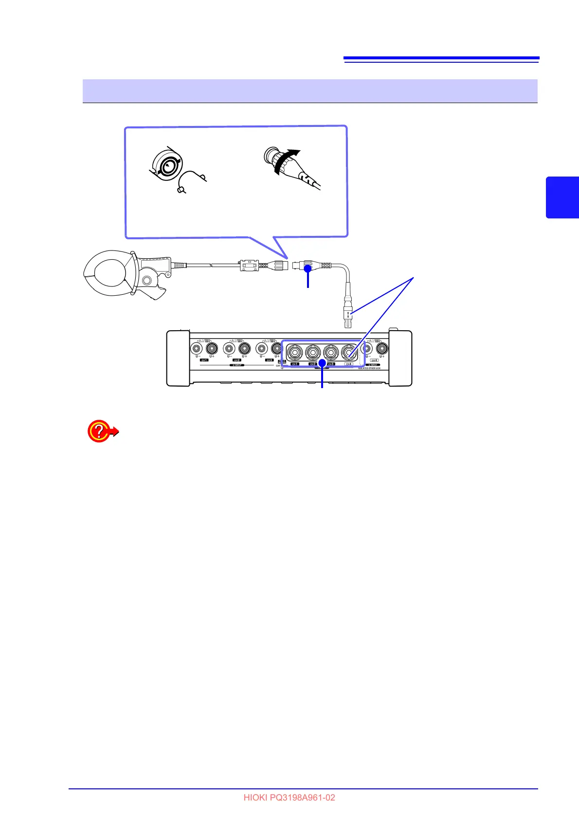
Connection Procedure: Current sensors other than the optional
12
Align the protrusions of the
connector with the groove,
and then insert it.
Turn the connector
clockwis
e to lock it
in place.
9661
L9910
Model L9910
Conversion Cable
Example: Model 9661 Clamp on Sensor
Use the L9910 Conversion Cable
to connect current sensors that
are not listed as options for the
instrument.
Align the arrow with the concave
part of the terminal to insert the
connector.
Current input terminal
To measure voltage and current beyond the range of the instrument or current sensor
Use an external VT (PT) or CT. By specifying the VT
or CT winding ratio on the instrument,
the input level at the primary side can be read directly.
See: "4.7 Quick setup" (p.66)
 Loading...


