Configure settings
(SYSTEM screen)
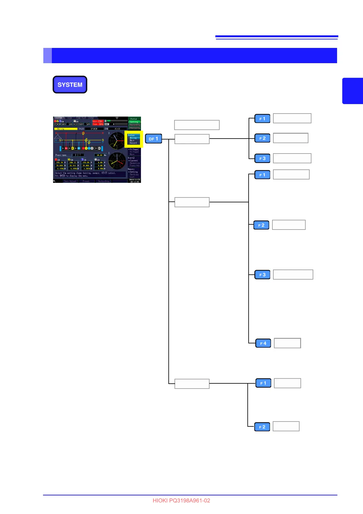
The [SYSTEM] screen is used to configure various instrument
settings.
Press the SYSTEM key to display the [SYSTEM] screen. The
screen can be changed with the DF keys.
Configures the connection,
current sensor, VT ratio, and
CT ratio settings. (This
screen is always displayed
after the instrument is turned
on.)
See: Chapter 4 (p.51)
Wiring
Main
Record
SYSTEM
Measure 1
Hardware
Zero Adjust
Preset
VectorArea
Configures the Recording
Items, TIME PLOT interval,
real-time control, and re-
peated recording settings.
See: 5.2 (p.75) to 5.3 (p.78)
Configures the connection, cur-
rent sensor, VT ratio, CT ratio,
and current range settings.
See: (p.71)
Configures the display lan-
guage, screen color, clock, ex-
ternal output, RS-connected
device, beep, and LCD back-
light settings. Resets the sys-
tem.
See: 5.4 (p.81)
See: 4.7 (p.66)
See: 4.1 (p.51)
Measure 2
Configures EVENT/TIME PLOT
settings, flicker, and filters.
See: (p.73)
LAN
Configures the LAN settings.
See:
Interval
Configures the recording, TIME
PLOT interval settings.
See: 5.2 (p.75)
Time
See: Configures the real-time
control, repeated record-
ing settings.5.3 (p.78)