3.7 Connecting the Current Sensors
46
Be sure to read the "Usage Notes" (p.7) before connecting current sensors.
Plug the current sensor cables into the current input jacks on the instrument (the number of connections
depends on the lines to be measured and selected wiring mode). See the instruction manual supplied
with the current sensor for specification details and usage procedures.
3.7 Connecting the Current Sensors
To prevent an electrical shock and bodily injury, do not touch any input terminals
on the VT (PT), CT or the instrument when they are in operation.
• When using an external VT (PT), avoid short-circuiting the secondary winding.
If voltage is applied to the primary when the secondary is shorted, high current
flow in the secondary could burn it out and cause a fire.
• When using an external CT, avoid open-circuiting the secondary winding. If
c
urrent flows through the primary when the secondary is open, high voltage
across the secondary could present a dangerous hazard.
• Phase difference in an external VT (PT) or CT can cause power measurement errors.
For optimum power measurement accuracy, use a VT (PT) or CT that exhibits mini
-
mal phase difference at the operating frequency.
• To ensure safety when using a VT (PT) or CT, one side of the secondary should be
g
rounded.
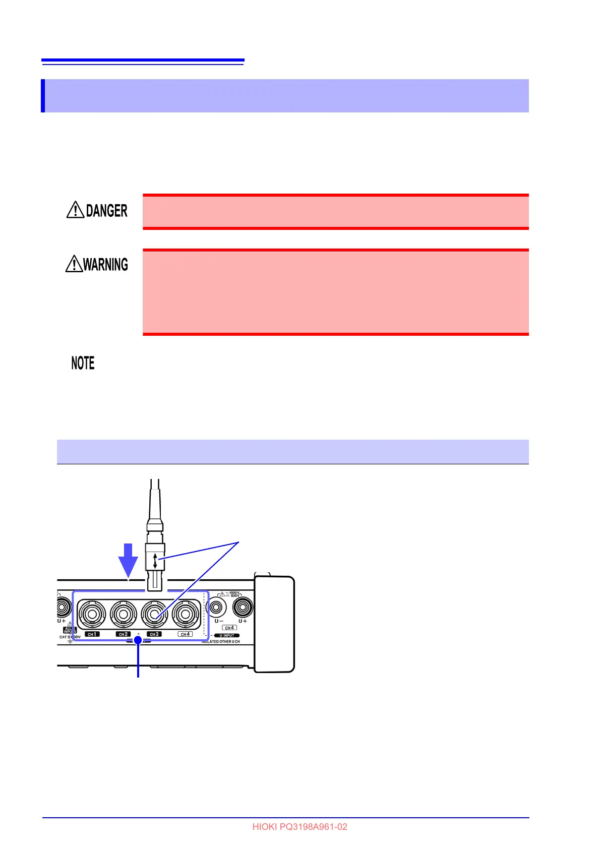
Connection Procedure: Optional current sensors
Align the arrow with the concave part of
the terminal to insert the connector.
Current input terminal
When disconnecting the current sensor,
be sure to grip the part of the connector
indicated by the arrows and pull it
straight out.