4.6 Verifying Correct Wiring (Connection Check)
64
Correct attachment to the lines is necessary for accurate measurements.
Check the measured values and vectors on the [SYS
TEM]-[Wiring] screen to verify that the con-
nections have been made properly. Refer to the measured values and vector displays to verify
th
at the measurement cables are correctly attached.
4.6 Verifying Correct Wiring (Connection Check)
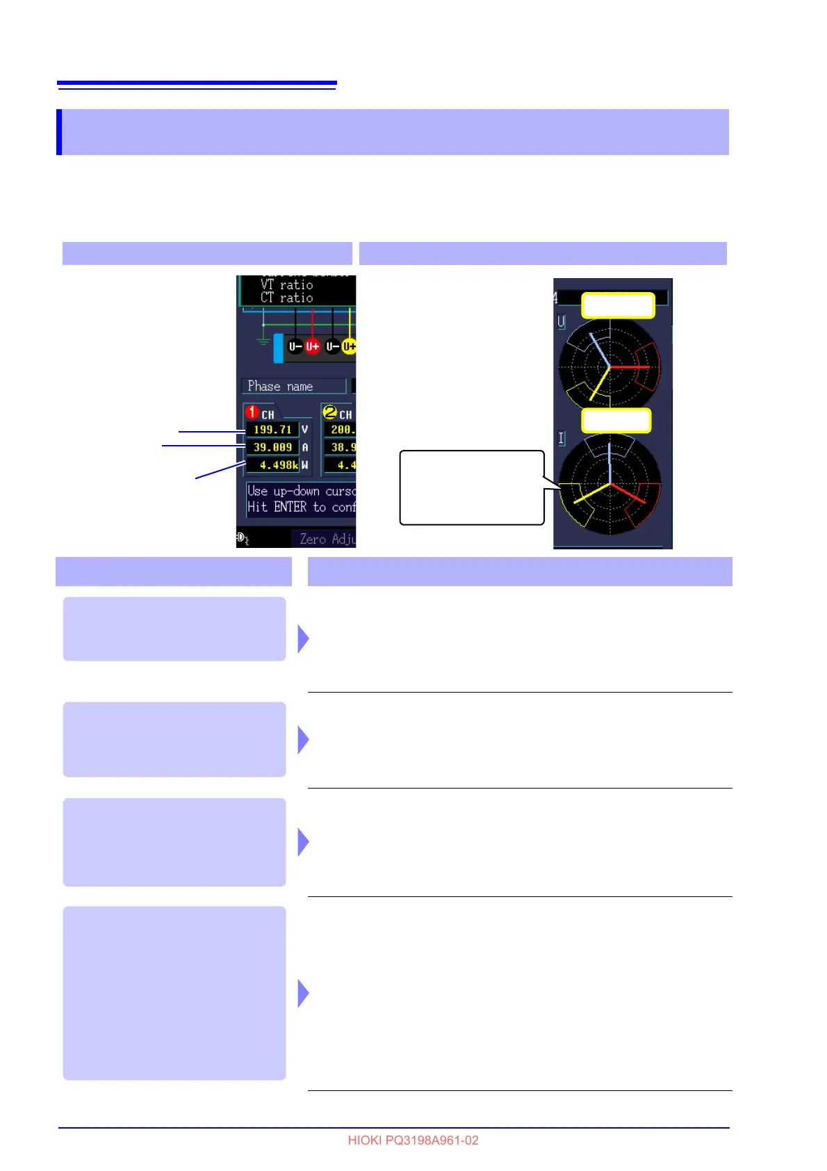
Verify that an appropri-
ate measurement value
is displayed.
Measured
voltage value
Measured
current value
Measured active
power value
Vector line range
Colors match the cor-
responding lines in the
wiring diagram.
For 1P2W systems
For systems other than 1P2W
• Verify that an appro-
priate measurement
value is displayed.
• Verify that the vec-
tors are displayed
with the appropriate
range.
In this case Check
• Are the cables securely plugged into the voltage measurement jacks on
the instrument? (p.45)
• Are the voltage measurement cable clips properly attached to the lines?
(p.61)
• Has the appropriate Urms type (phase voltage/line voltage) been
selected? (p.73)
• Are the current sensors securely plugged into the current measurement
jacks on the instrument? (p.46)
• Are the current sensors properly attached to the lines? (p.62)
• Are the current sensors appropriate for th
e line current to be measured?
• Have the sensor’s range settings
been configured appropriately?
• Are the current sensors properly attached to the lines? (p.61)
• Is the arrow marker on the current sensors pointing toward the load?
(p.62)
• During 3P3W2M measurement, the active power of each channel can
become ne
gative in some cases, for example, if a circuit under measure-
ment has a power factor of 0.5 or less.
Voltage vectors:
• Are the cables securely plugged into voltage measurement jacks on the
instrument? (p.45)
• Are the voltage measurement cable cli
ps properly attached to the lines?
(p.61)
Current vectors:
• Are the current sensors securely plugged into the current measurement
jacks on the instrument? (p.46)
• Are the current sensors properly attached to the lines? (p.62)
• Are the current sensors appropriate for the line current to be measured?
• Is the sensor range set correctly?
A measured value is too high or
too low compared to the set
[Udin].
If the measured current value is
not correct.
If the measured active power value
is negative.
If vectors are too short, or unequal.