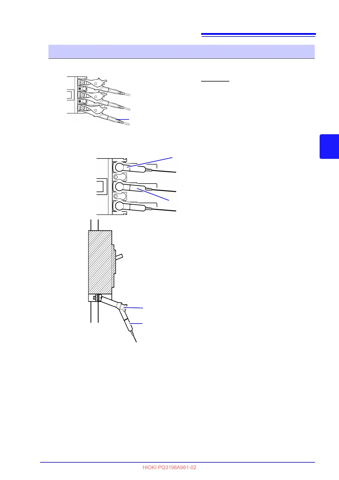
Securely clip the leads to metal parts such as terminal screw ter-
minals or bus bars.
Example: Secondary side of breaker
Model L1000 Voltage Cord
Example: When using Model 9804-01 or 9804-02 Magnetic Adapter (standard screw: M6 pan head screw)
Secondary side of
breaker
Model 9804-01, 9804-02 Magnetic Adapter
Model L1000
Voltage Cord
Secondary side of
breaker
Model L1000 Voltage Cord
Model 9804-01, 9804-02 Magnetic Adapter
Attach the Model 9804-01 or 9804-02
Magnetic Adapter (option) to the Model
L1000 Voltage Cord.
Connect the magnetic part of the 9804-
01 or 9804-02 tip to the screws on the
secondary side of the breaker.
The weight of the voltage cords may prevent you from making a
perpendicular connection to the Model 9804-01 or 9804-02 Mag-
netic Adapter. In this case, connect each cords so that it is hang-
ing off the adapter in a manner that balances its weight.
Check the voltage values to verify that the connections have been
made securely.
 Loading...


