4.7 Quick setup
67
Chapter 4 Configuring the Instrument before Measurement (SYSTEM - SYSTEM screen) and
Wiring
4
Type of measurement lines
Set before proceeding to the next step.
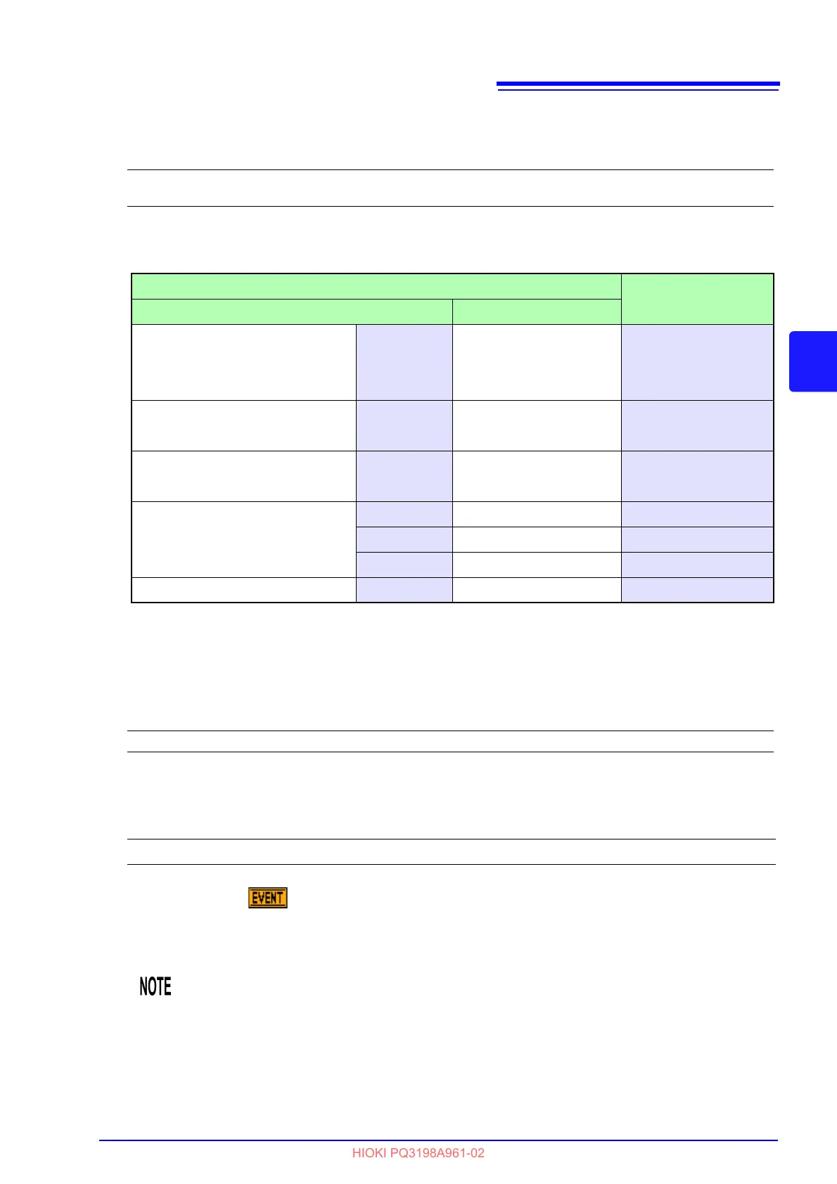
Current sensor used
Set before proceeding to the next step.
*: Set the range switch of the sensor to
500 A when the current range of this instrument is set to 500 A or
50 A.
External VT Ratio, External CT Ratio
Set when attaching an external VT or CT. Set to 1 if not attaching an external VT or CT.
TIME PLOT Interval
Sets the TIME PLOT interval.
If the event icon ( ) is orange after performing quick setup (indicating that the event is being
detected continuously), it is recommended to check and reconfigure the event's threshold.
See:"5.6Changing Event Settings" (p.85)
Setting Contents:
CH1,2,3: 1P2W/1P3W/3P3W2M/3P3W3M/3P4W/3P4W2.5E
CH4: ACDC/DC/OFF
Current sensor
Current range
Optional Other than the optional
AC flexible current sensor
CT7044 CT9667-01*
5000 A, 500 A, 50 ACT7045 CT9667-02*
CT7046 CT9667-03*
AC leakage current sensor CT7116
9657-10
5 A, 500 mA
9675
AC current sensor CT7126
9694
50 A, 5 A
9695-02
AC/DC auto-zero current sensor
CT7731 - 100 A, 50 A
CT7736 - 500 A, 50A
CT7742 - 5000 A, 500 A
Clamp on sensor - 9669 1000 A, 100 A
Setting Contents:
0.01 to 9999.99
Setting Contents:( ∗ : Default setting)
1/ 3/ 15/ 30 second(s), 1∗/ 5 /10/ 15/ 30 minute(s), 1/2 hour(s), 150/180cycle
The 150 (50 Hz) and 180 (60 Hz) cycle settings provide the TIME PLOT intervals
required for IEC61000-4-30-compliant measurement. When using a measurement fre
-
quency of 400 Hz, selecting 150/180 cycle will result in a 1200 cycle interval.