Redundancy
RM Web L3P
Release
4.1
03/08
8.3
Redundant coupling
143
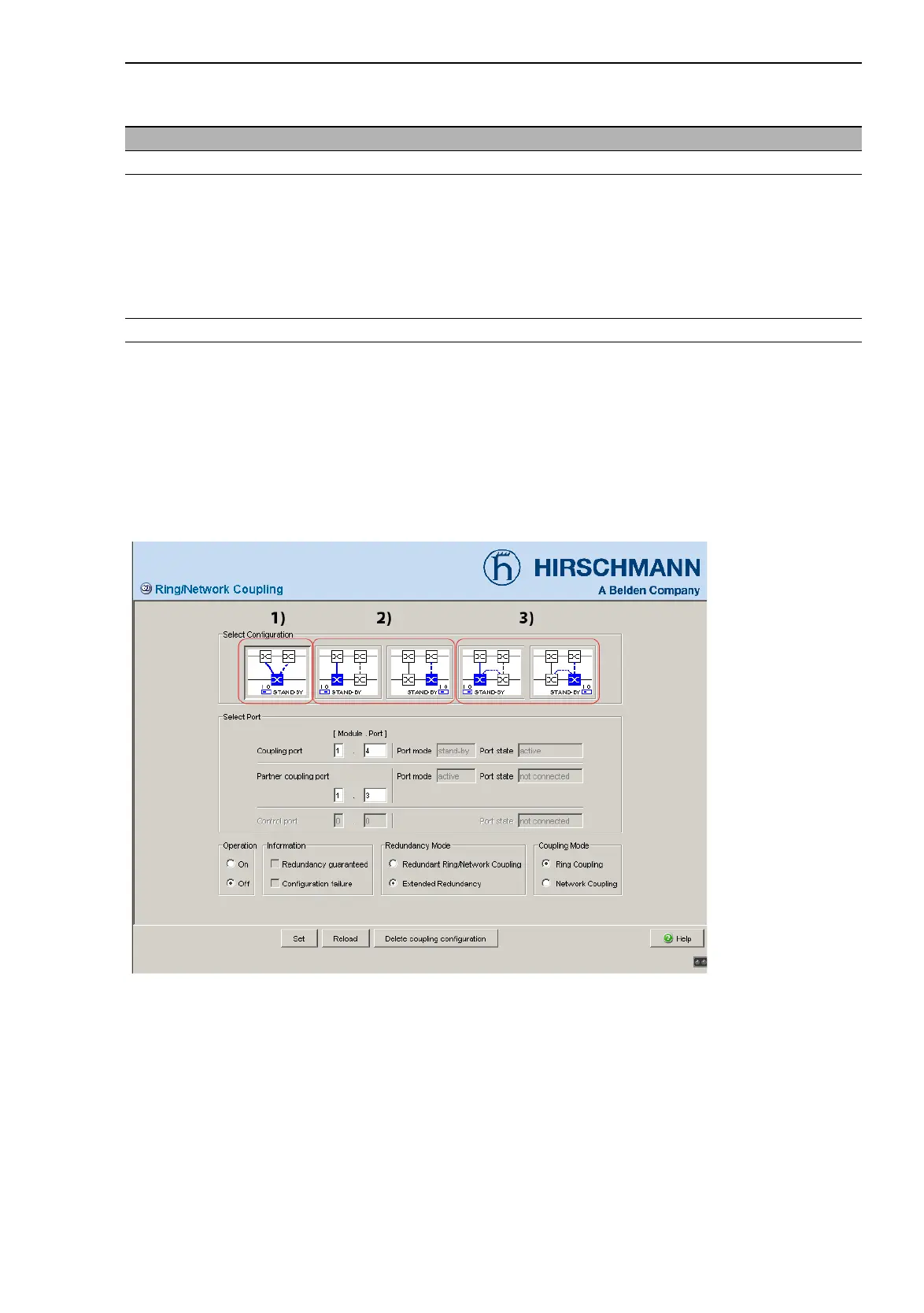
Select the Redundancy:Ring/Network Coupling dialog.
You first select the configuration you want: One-Switch coupling (“1”),
two-Switch coupling (“2”) or two-Switch coupling with control line (“3”),
(see fig. 46).
Figure 46: Selecting the configuration
Note: Depending on the STAND-BY DIP switch position, the dialog dis-
plays those configurations that are not possible in gray. If you want to se-
lect one of these grayed-out configurations, you put the STAND-BY DIP
switch on the Switch into the other position.
Switch with Choice of main coupling or redundant coupling
DIP switch “STAND-BY” on DIP switch
DIP switch/software switch
option
According to the option selected
- “Stand-by” on the DIP switch or in the
- Redundancy:Ring/Network Coupling dialog, by selecting in
“Select configuration”.
Note: These devices have a DIP switch, with which you can choose
between the software configuration and the DIP configuration. If the
software configuration is set, the other DIP switches have no effect.
Software switch In the Redundancy:Ring/Network Coupling dialog
Table 28: Choice of main coupling or redundant coupling
 Loading...