Faxitron CT Specimen Radiography System User Guide
Chapter 3: Components, Controls, and Indicators
5081-9544 Revision 004 Page 27
3.2 System Connections
Power and Network Connections
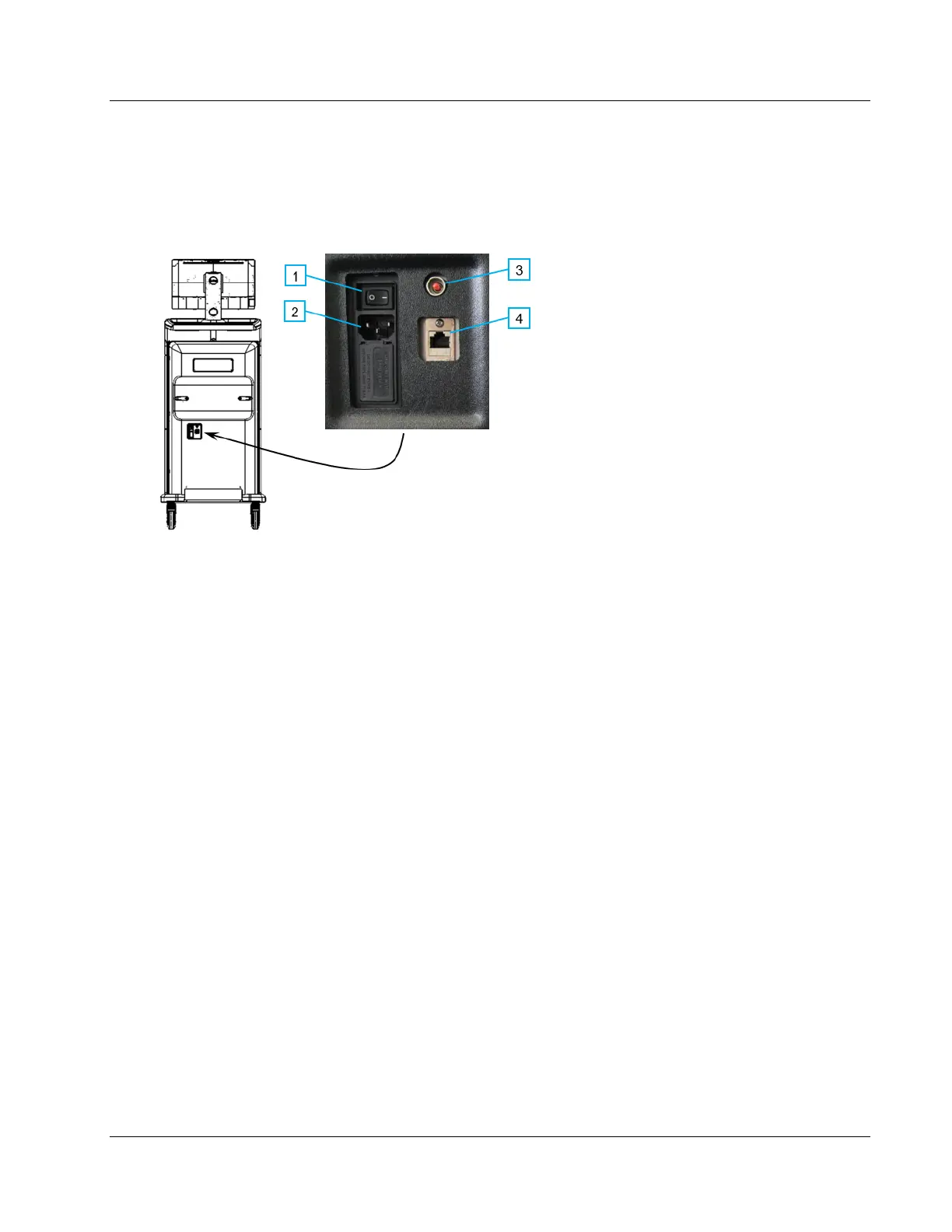
Figure 11: Power and Network Connections
Figure Legend
1. System Power Switch
2. Power Cord Connection
3. Computer Reset Button
4. Ethernet Port
1. Put the system in a location where you can easily access power connections and
network connections.
2. Connect the system power cord to the electrical outlet.
3. If desired, connect the network cable to the ethernet port.
USB Connections
The console has two USB ports located at the back of the control display.
Additionally, there are 2 USB ports on the left side of the monitor.