ENGINEERING MANUAL OF AUTOMATIC CONTROL
PNEUMATIC CONTROL FUNDAMENTALS
90
PNEUMATIC CONTROL SYSTEM EXAMPLE
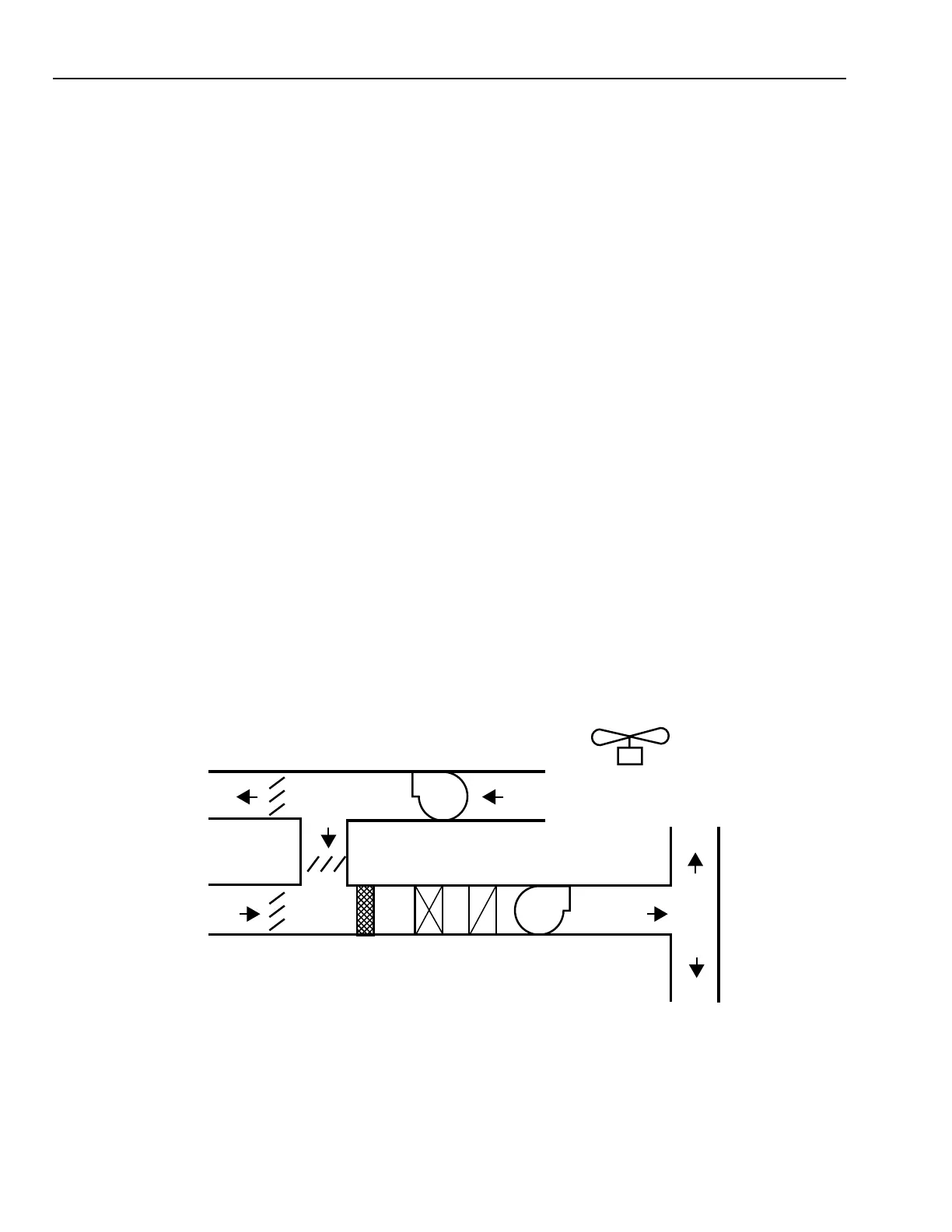
The following is an example of a typical air handling system
(Fig. 74) with a pneumatic control system. The control system
is presented in the following seven control sequences (Fig. 75
through 79):
— Start-Stop Control Sequence.
— Supply Fan Control Sequence.
— Return Fan Control Sequence.
— Warm-Up/Heating Coil Control Sequence.
— Mixing Damper Control Sequence.
— Discharge Air Temperature Control Sequence.
— Off/Failure Mode Control Sequence.
Controls are based upon the following system information
and control requirements:
System Information:
— VAV air handling system.
— Return fan.
— 16.5 m
3
/s.
— 1.9 m
3
/s outside air.
— 1.4 m
3
/s exhaust air.
— Variable speed drives.
— Hot water coil for morning warm-up and to prevent
discharge air from getting too cold in winter .
— Chilled water coil.
— Fan powered perimeter VAV boxes with hot water reheat.
— Interior VAV boxes.
— Water-side economizer.
— 8:00 A.M. to 5:00 P.M. normal occupancy.
— Some after-hour operation.
GRAVITY
RELIEF
RETURN
AIR
RETURN FAN
SUPPLY FAN
EAST
ZONE
DISCHARGE
AIR
WEST
ZONE
MIXED
AIR
OUTSIDE
AIR
EXHAUST
M10298
Control Requirements:
— Maintain design outside air airflow during all levels of
supply fan loading during occupied periods.
— Use normally open two-way valves so system can heat
or cool upon compressed air failure by manually running
pumps and adjusting water temperatures.
— Provide exhaust/ventilation during after-hour occupied
periods.
— Return fan sized for 16.5 m
3
/s.
START-STOP CONTROL SEQUENCE
Fans 1M through 3M (Fig. 75) operate automatically subject
to starter-mounted Hand-Off-Automatic Switches.
The Supply Fan 1M is started and controls are energized by
Electric-Pneumatic Relay 2EP at 0645 by one of the following:
— An Early Start Time Clock 1TC
— A drop in perimeter space temperature to 18°C at Night
Thermostat TN
— An after-hour occupant setting the Spring-Wound Interval
Timer for 0 to 60 minutes.
The Supply Fan 1M operation is subject to manually reset
safety devices including Supply and Return Air Smoke
Detectors; a heating coil, leaving air, Low Temperature
Thermostat; and a supply fan discharge, duct High Static
Pressure Cut-Out.
Fig. 74. Typical Air Handling System.