ENGINEERING MANUAL OF AUTOMATIC CONTROL
CHILLER, BOILER, AND DISTRIBUTION SYSTEM CONTROL APPLICATIONS
382
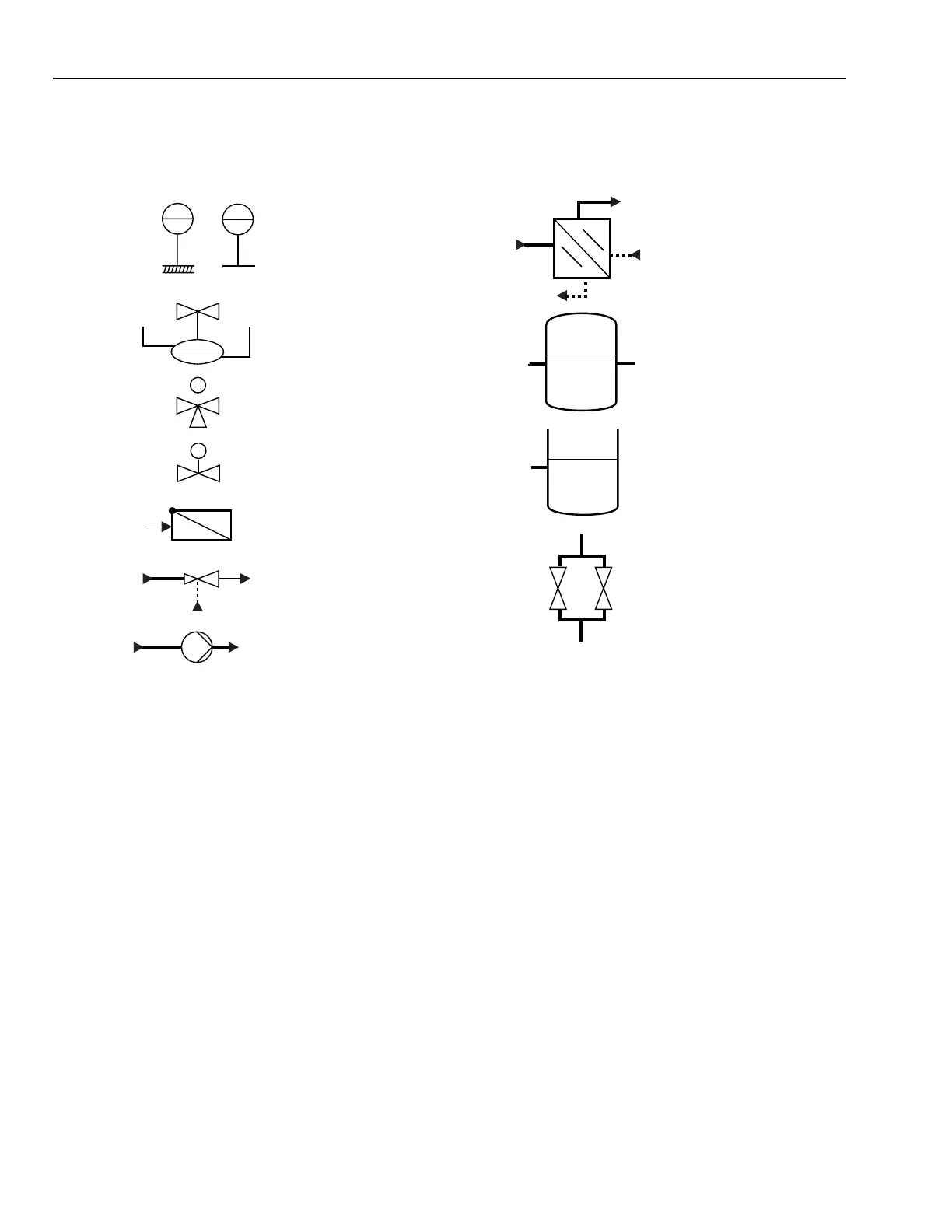
SYMBOLS
Since District Heating is more common in Europe, District Heating is based on information supplied by personnel in Europe.
The symbols used in Figures 126 through 143 are those commonly used in Europe and are supplied here for convenience.
PUMP, AIR OR WATER
THREE-WAY VALVE
TWO-WAY VALVE
CHECK VALVE
M
HEAT EXCHANGER
DIFFERENTIAL PRESSURE CONTROL
WATER STORAGE TANK
EXPANSION TANK
TI
01
OUTSIDE AIR
TI
31
ROOM
TEMPERATURE SENSORS
SURGE TANKS
M
JET PUMP
FLOW
M10674
SYSTEM CONFIGURATION
HEAT GENERATION
Excess heat is produced in steam electrical power generating
stations which can be reclaimed as in Figure 126 and sold to
provide heat for other uses. Other industrial processes and waste
incineration may also provide a source of excess heat which
can be reclaimed. Geothermal sources and boilers are other
heat sources.
HEAT DISTRIBUTION NETWORK
The distribution network is one part of a district heating
system. It transports the heat from the heat source to the
consumer. Heat is absorbed by the heat transfer medium, hot
water or steam, at the source and delivered to the consumer.
Primary networks are one- or two-pipe distribution systems.
In a two-pipe system the hot pipe, or supply line, transports the
water or steam to the substation, heat is drawn from the network
at the substation and transferred to the consumer’s side, then
the cooled water or condensate flows through the return line
back to the heat source to be re-heated.
A one-pipe system transports the water to the consumer, heat
is drawn from the network at the substation and transferred to
the consumer’s side, then the cooled water is discharged to a
drain. This system is used with a geothermal hot water source.
HOT WATER SYSTEM CONTROL
Variable speed circulating pumps move the water through
the primary network providing the needed differential pressure
in hot water systems. An additional pressure holding system is
installed to keep the absolute pressure at the required level.
There are two control strategies based on outdoor air
temperature for transferring a requested amount of heat to the
consumer:
1. Constant Flow Control maintains a constant supply flow
rate and varies supply flow temperature.
2. Variable Flow Control maintains a constant supply flow
temperatures and varies supply flow rate.
 Loading...


