INDIVIDUAL ROOM CONTROL APPLICATIONS
ENGINEERING MANUAL OF AUTOMATIC CONTROL
423
INDIVIDUAL ROOM CONTROL AUTOMATION
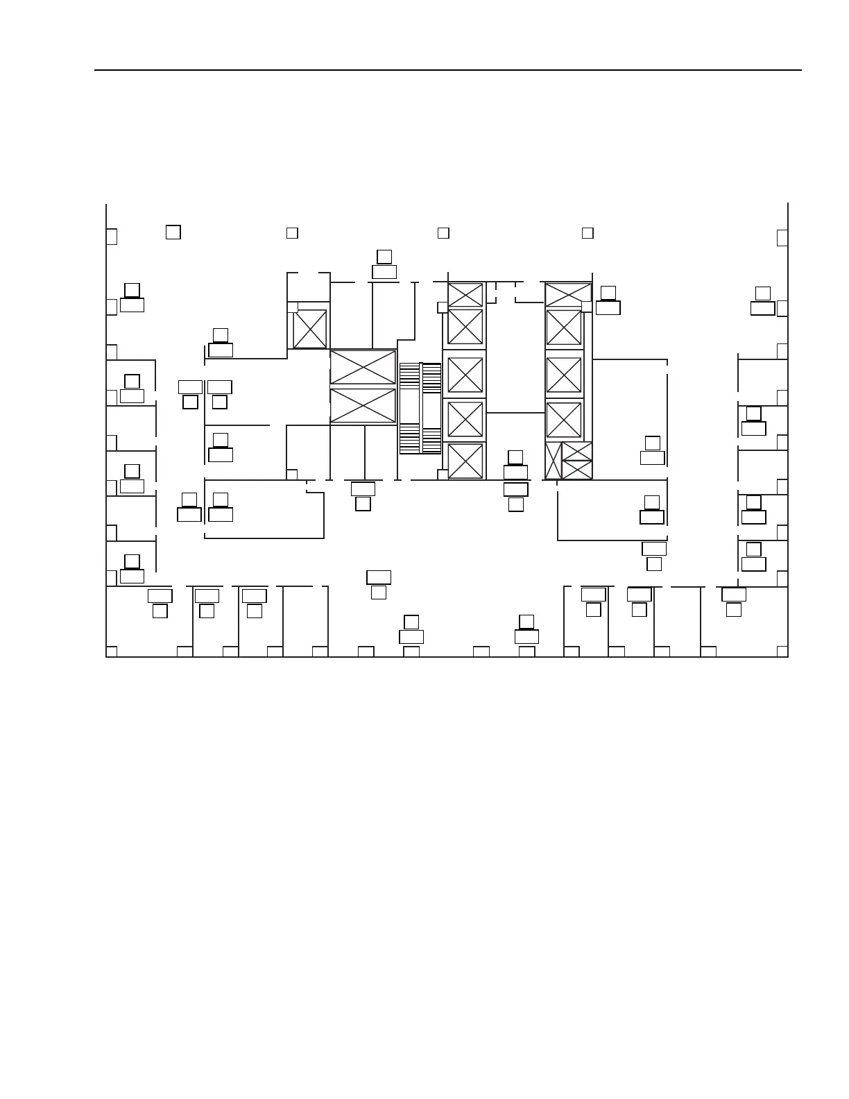
On automa ted jobs with a g raphic BMS , ATUs ar e usuall y
shown on a f loor plan similar to F igure 39.
The Figur e 39 example sho ws a graphic of the souther n half
of a floor with 30 VAV boxes and their associa ted space
temper atur es. Selecting an y VAV box would pr oduce a g raphic
of tha t box, similar to those pr eviously shown in this section,
and all specif ied da ta suc h as space temper atur e setpoints,
minimum and maximum airflow setpoints, etc.
Fig. 39. ATU System Floor Plan Graphic
= VAV BOX
MEN
ELEVATOR
LOBBY
M10532
V
23.7
V
23.7
V
23.7
V
23.7
V
23.7
V
23.7
V
23.7
V
23.7
V
23.7
V
23.7
V
23.7
V
23.7
V
23.7
V
23.7
V
23.7
V
23.7
V
23.7
V
23.7
V
V
23.7
V
23.7
V
23.7
V
23.7
V
23.7
V
23.7
V
23.7
V
23.7
V
23.7
V
23.7
V
23.7
V
23.7
V
23.7
TENTH FLOOR SOUTH