PNEUMATIC CONTROL FUNDAMENTALS
ENGINEERING MANUAL OF AUTOMATIC CONTROL
81
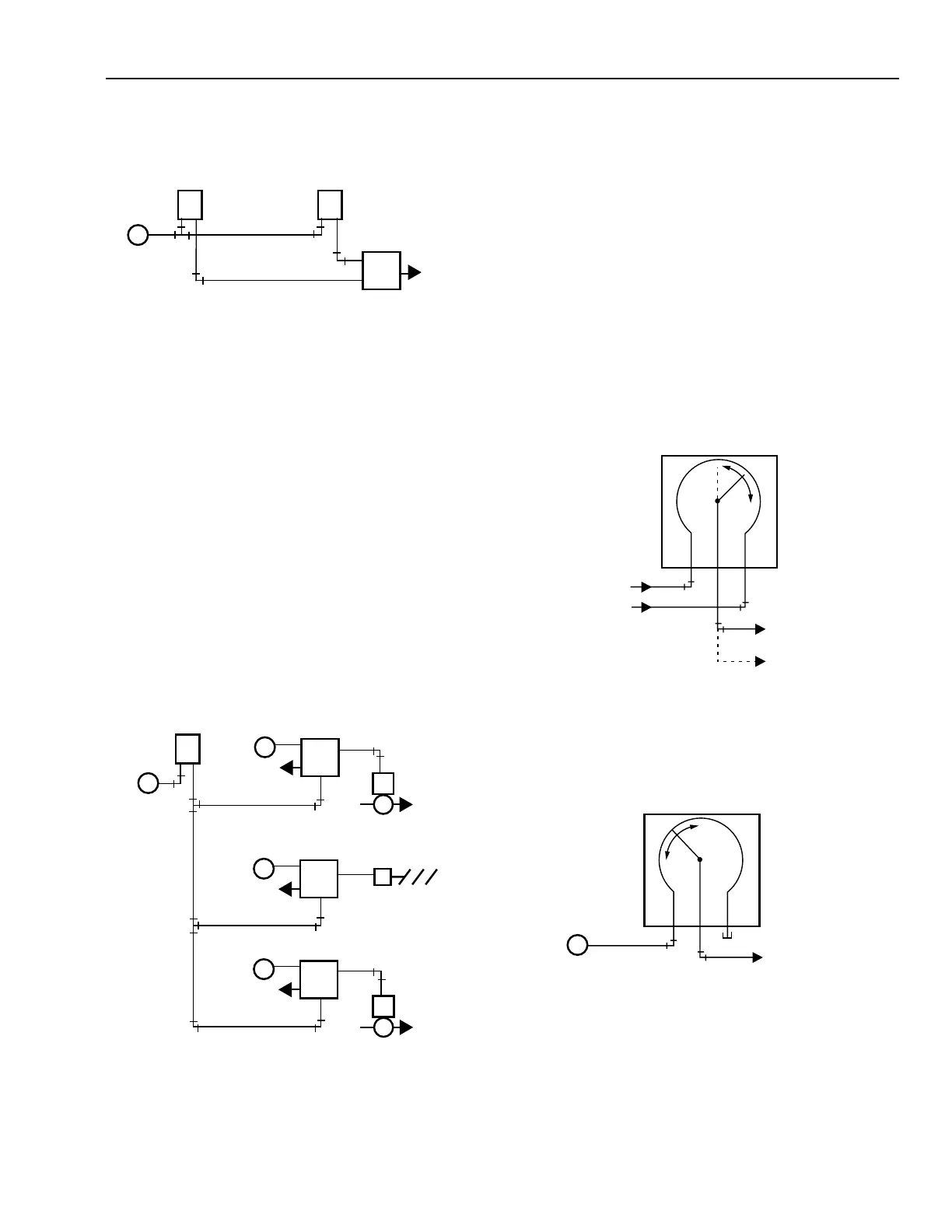
Figure 45 shows an averaging relay in a typical application
with two thermostat signals as inputs. The average of the
thermostat signals controls a valve or damper actuator.
Fig. 45. Averaging Relay Application.
RATIO RELAY
The ratio relay is a four-port, non bleed relay that produces a
modulating pressure output proportional to the thermostat or
controller branchline output. Ratio relays can be used to control
two or three pneumatic valves or damper actuators in sequence
from a single thermostat. The ratio relay has a fixed input
pressure range of either 20 or 35 kPa for a 70 kPa output range
and an adjustable start point. For example, in a ratio relay with
a 35 kPa range set for a 50 kPa start, as the input pressure
varies from 48 to 83 kPa (start point plus range), the output
pressure will vary from 20 to 90 kPa.
In Figure 46, three 20 kPa span ratio relays are set for 20 to 40,
40 to 60, and 60 to 80 kPa inputs, respectively. The thermostat
signal through the relays proportions in sequence the three valves
or actuators that have identical 20 to 90 kPa springs.
PNEUMATIC POTENTIOMETER
The pneumatic potentiometer is a three-port, adjustable linear
restrictor used in control systems to sum two input signal values,
average two input pressures, or as an adjustable flow restriction.
The potentiometer is a linear, restricted air passage between
two input ports. The pressure at the adjustable output port is a
value based on the inputs at the two end connections and the
location of the wiper between them.
Figure 47 shows a pneumatic potentiometer providing an
average of two input signals. The wiper is set at mid-scale for
averaging or off-center for a weighted average. It can be used
this way to average two air velocity transmitter signals from
ducts with different areas by positioning the wiper according
to the ratio of the duct areas. This outputs a signal proportional
to the airflow.
SIGNALS
FROM
SENSORS
WEIGHTED
AVERAGE
SIGNAL
AVERAGE
SIGNAL
C2374
PNEUMATIC POTENTIOMETER
INPUT 1
OUTPUT
INPUT 2
Fig. 47. Pneumatic Potentiometer as Averaging Relay.
Figure 48 shows a pneumatic potentiometer as an adjustable
airflow restrictor.
THERMOSTAT 2
THERMOSTAT 1
AVERAGING
RELAY
C2345
M B
M B
P
2
B
P
1
TO
ACTUATOR
M
Fig. 46. Ratio Relays in Sequencing Control Application.
Fig. 48. Pneumatic Potentiometer as
Adjustable Airflow Restrictor.
TO
CONTROLLED
DEVICE
C2372
PNEUMATIC POTENTIOMETER
INPUT 1
OUTPUT
INPUT 2
M
CAP
C4222
RATIO RELAY 1
20-40 kPa
HEATING
VALVE
20-90 kPa
MIXING
DAMPERS
20-90 kPa
COOLING
VALVE
20-90 kPa
DA ZONE
THERMOSTAT
M B
EXH
M
RATIO RELAY 3
60-80 kPa
EXH
M
M
M
E
B
P
RATIO RELAY 2
40-60 kPa
EXH
M
M
E
B
P
M
E
B
P