INDIVIDUAL ROOM CONTROL APPLICATIONS
ENGINEERING MANUAL OF AUTOMATIC CONTROL
401
An economical alter native to reheating air tha t has been
cooled or reducing the reheat requirement is to reset the setpoint
of pr imar y air in the centr al fan system conditioning section.
Primary air reset limits are usually required to assure adequate
dehumidif ication.
The VAV ATU configur ations in F igures 5 thr ough 9 ar e
pressure-independent.
Variable Air Volume ATU
The var iable air volume ATU (Fig. 5) is a pr essure-
independent unit w hich delivers the r equir ed air v olume to the
space r egar dless of the suppl y static pr essur e. The amount of
air deli vered is der ived from a space temper atur e PI loop. A
flow sensor in the suppl y airf low modula tes the damper actua tor
to contr ol air v olume. The room sensor r esets the airf low
setpoint as the space ther mal load c hang es. The airf low contr ol
loop can be set to maintain minim um airf low at light load
conditions, while, maxim um airf low can be set to limit f low to
meet design conditions. A single wall module can be dir ected
to multiple contr ollers to contr ol multiple ATUs with the same
or dif fering volume r atings.
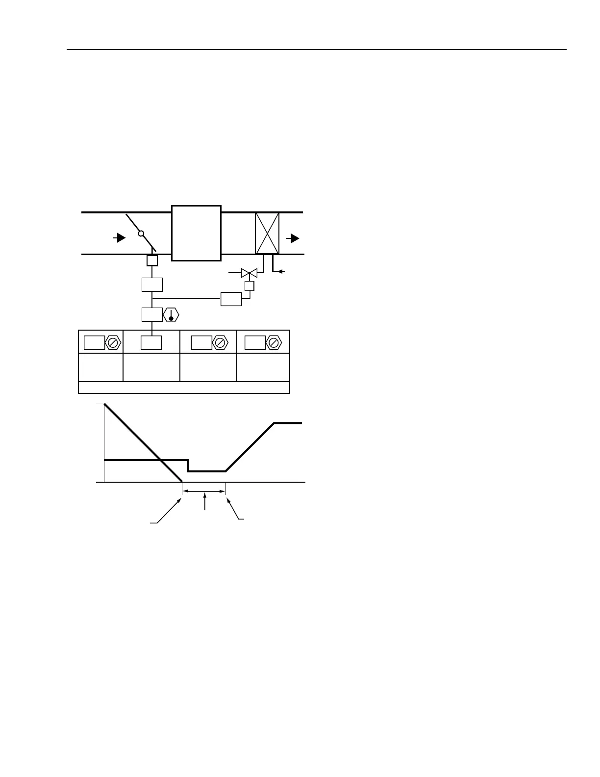
Figur e 4 shows a r eheat coil ad ded to a thr ottling VAV ATU.
In this application, the temperature controller sequences the
oper ation of the damper actua tor and the contr ol valve or r eheat
coil. The coil can be r eplaced b y single or m ultiple sta ges of
electr ic resistance hea t. The damper modula tes under PI contr ol
at the cooling setpoint and the hot water valve modulates under
a separate PI control at the heating setpoint, with a deadband
between heating and cooling. In this example, the space
occupant can adjust the wall module temperature cooling
setpoint (displa yed as SPACE TEMPERA TURE in the setpoint
schedule) and the BMS operator can adjust for the deadband
between cooling and heating.
Fig. 4. Throttling VAV Air Terminal
Unit with Reheat Coil.
M15305
24
74
00
24 24 77
MINIMUM
DAMPER
POSITION
MAXIMUM
DAMPER
POSITION
-2.5
HEATING
DEADBAND
CURRENT
TEMPERATURE
SPACE
TEMPERATURE
SETPOINT SCHEDULE
OPEN
ACTUATOR
POSITION
CLOSED
MINIMUM
POSITION
REHEAT
POSITION
MAXIMUM
POSITION
LOWHIGH
VALVE
DAMPER
RHC
LOW
HIGH
SPACE
HEATING LOAD
HEATING SETPOINT
COOLING SETPOINT
SPACE
COOLING LOAD
DEADBAND
PERCENT
OPEN
PERCENT
OPEN
PRIMARY
AIR
 Loading...


