BUILDING MANAGEMENT SYSTEM FUNDAMENTALS
ENGINEERING MANUAL OF AUTOMATIC CONTROL
193
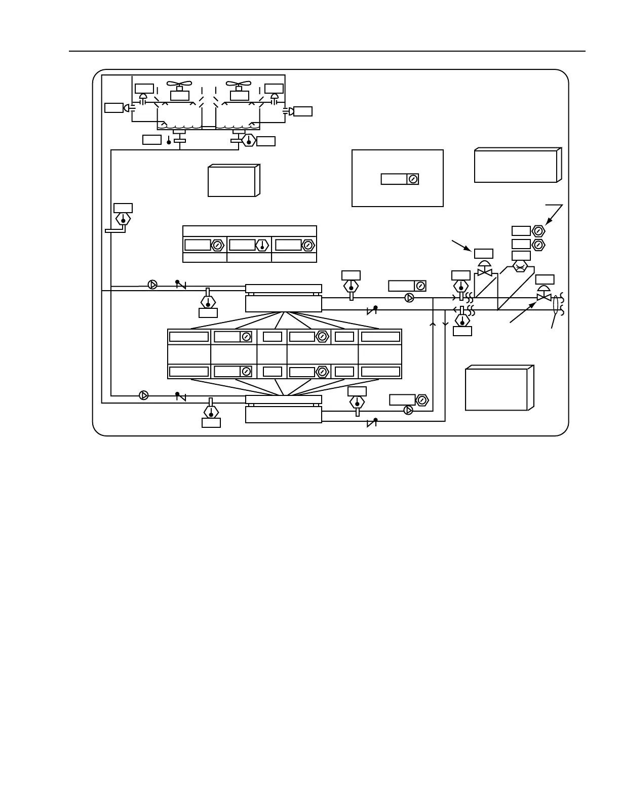
Fig. 7. Graphic Sketch for Sequence of Operation.
SPECIFYING GRAPHICS (I/O SUMMARIES)
When writing the control sequence of operation, sketch the
graphic (Fig. 7) and note the necessary inputs and outputs
required for control. Develop an Input/Output (I/O) Summary
(Fig. 8) where, the X-axis lists generic types of points and the
Y-axis lists the specific points. Publishing the graphic sketch
with all hardware and software points and symbols is an
excellent alternative to the I/O summary.
0
0
100
33
33
100
33
7
00
13.0
26
7.3
13
30
ON
OFF
100
100
78 NORMALENABLED
ENABLED
BY REMOTE
CONTROLS
OPERATING
MODE
ALARM
STATUS
MAX
CURRENT
STATUS
NORMAL00
AUTO
MINIMUM
CHILLED WATER SETPOINT
MAXIMUMACTUAL
AUTO
1
AUTO
AUTO
7 8 11
100
PRESSURE
CHOKE
VALVE
CHILLER
CONTROL
SETPOINTS/
SEQUENCES
365
TO
AHUs
kPa
PRESSURE
BYPASS
VALVE
DUAL CHILLER
SETPOINT
REDUCTION
LEAD CHILLER
SELECTOR
PRESSURE BYPASS
& CHOKE VALVE
CONTROL
1 = CHILLER 1 LEADS
2 = CHILLER 2 LEADS
COOLING
TOWER
CONTROL
26
DUAL CHILLER PLANT
CONTROL
GRAPHIC DISPLAY
M15136
CHILLER 1
CHILLER 2
%
LOAD
365
26
72.4