ENGINEERING MANUAL OF AUTOMATIC CONTROL
PNEUMATIC CONTROL FUNDAMENTALS
82
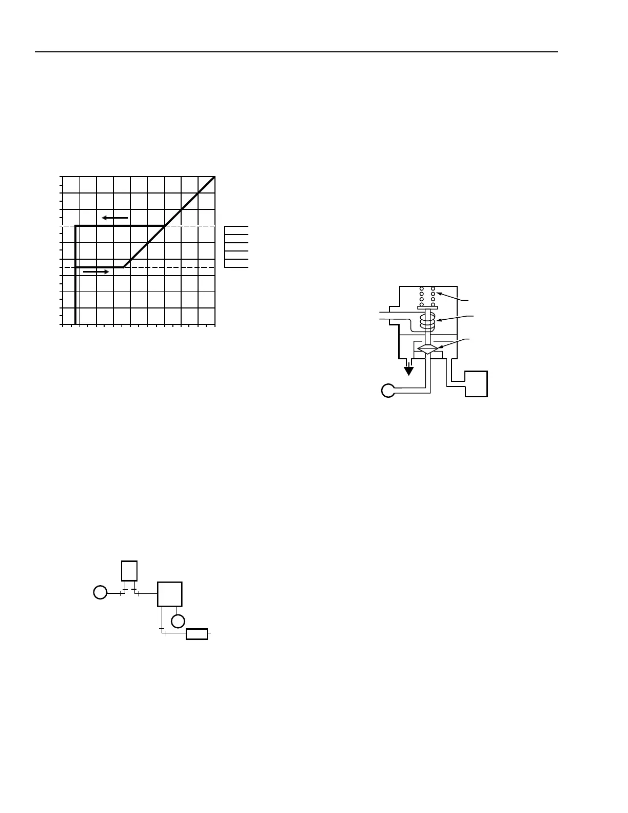
HESITATION RELAY
The hesitation relay is used with a pneumatic actuator in unit
ventilator applications. The output pressure goes to minimum
whenever the input pressure is below the minimum setting.
Figure 49 shows a graph of the output of a hesitation relay as
controlled by the relay knob settings (piloted from the
thermostat).
M
MB
M
P
B
M
DA ROOM
THERMOSTAT
HESITATION
RELAY
DAMPER
ACTUATOR
C2346
Fig. 49. Hesitation Relay Output Pressure
as a Function of Knob Setting.
The hesitation relay has an internal restrictor. Figure 50 shows
a typical application of a hesitation relay and a pneumatic
damper actuator. When the thermostat branchline pressure
reaches 10 kPa, the relay output goes to its preset minimum
pressure. When the branchline pressure of the thermostat
reaches the setting of the hesitation relay, the thermostat controls
the damper actuator. When the thermostat branchline pressure
drops below the hesitation relay setting, the relay holds the
damper actuator at the minimum position until the thermostat
branchline pressure drops below 10 kPa. At that point, the
hesitation relay output falls to zero.
ELECTRICAL INTERLOCKING RELAYS
Electrical interlocking relays bridge electric and pneumatic
circuits. The electric-pneumatic relay uses electric power to
actuate an air valve in an associated pneumatic circuit. The
pneumatic-electric relay uses control air pressure to make or
break an associated electrical circuit.
ELECTRIC-PNEUMATIC RELAY
The electric-pneumatic (E/P) relay is a two-position, three-
way air valve. Depending on the piping connections to the ports,
the relay performs the same functions as a simple diverting
relay. A common application for the E/P relay is to exhaust and
close an outdoor air damper in a fan system when the fan motor
is turned off, as shown in Figure 51.
M
FAN
INTERLOCK
VOLTAGE
EXH
OXC
OUTDOOR
AIR DAMPER
ACTUATOR
PLUNGER
RELAY COIL
SOLENOID
SPRING
E/P RELAY
C2602
Fig. 51. E/P Relay Application.
When the relay coil is de-energized, the solenoid spring seats
the plunger. The normally disconnected port (X) is blocked
and the normally connected port (O) connects to the common
port (C). The connection exhausts the damper actuator which
closes the damper. When the relay coil is energized, the plunger
lifts against the tension of the spring and blocks the normally
connected port (O). Main air at the normally disconnected port
(X) connects to the common port (C) and opens the damper.
PNEUMATIC-ELECTRIC RELAY
Figure 52 shows a simplified pneumatic-electric (P/E) relay
with a spdt switch. The P/E relay makes the normally closed
contact on a fall in pilot pressure below the setpoint, and makes
the normally open contact on a rise above a value equal to the
setpoint plus the differential. For example, with a setpoint
adjustment of 21 kPa and a differential of 14 kPa, the pump is
energized at pilot pressures below 20 kPa and turns off at pilot
pressures above 35 kPa.
Fig. 50. Typical Hesitation Relay Application.
C4223
RELAY INPUT (kPa)
0
14
28
41
55
69
83
97
110
124
48
0 14284155698397111125
RELAY OUTPUT (kPa)
100
80
60
40
20
0
KNOB SETTING (%)