ENGINEERING MANUAL OF AUTOMATIC CONTROL
CHILLER, BOILER, AND DISTRIBUTION SYSTEM CONTROL APPLICATIONS
346
As flow through the system is reduced, a new system curve
is established. See the 0.375 L/s curve in Figure 69. When the
flow is reduced, the new pressure loss in source and supply and
return piping can be calculated using the formula:
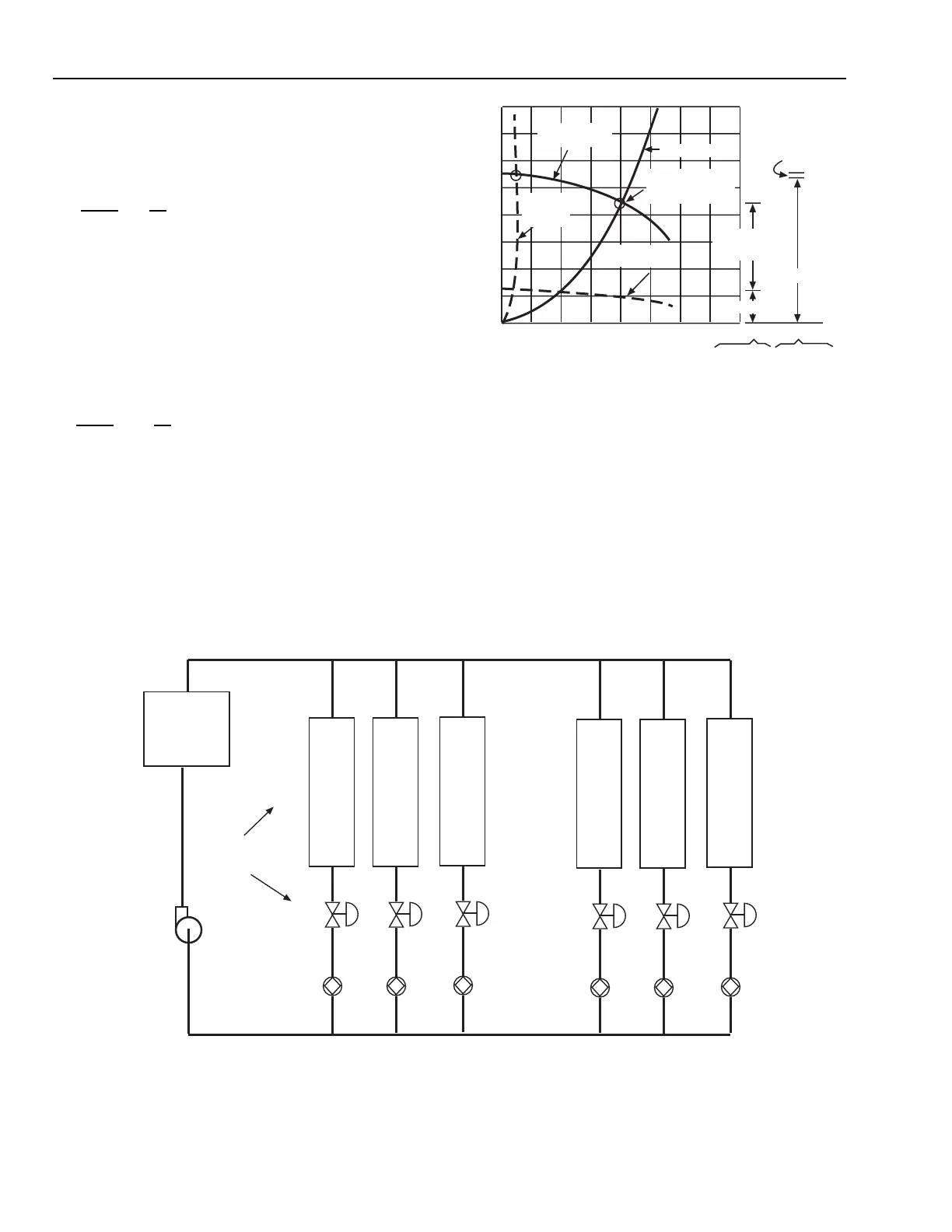
Fig. 70. Direct Return Piping System
Where:
flow
1
= present flow
flow
2
= next flow
p
1
= present pressure drop
p
2
= next pressure drop
For example: If flow
1
= 2.5 L/s, flow
2
= 0.375 L/s, and p
1
=
99 kPa, then p
2
= 2.2 kPa.
p
2
= 99 x 0.0225
= 2.2 kPa
At low flow, the pressure drops through the coils, coil piping,
and heat source tend to disappear and nearly all of the now
elevated pump pressure appears across the partially closed
valves V1, V2, and V3. This can cause valve noise, poor control,
or failure of valves to seat. Control solutions are discussed in
following sections.
Fig. 69. System and Pump Curves for a
Closed System at Various Loads.
DIRECT VS REVERSE RETURN PIPING SYSTEMS
Distribution system control solutions vary dependent upon
whether the designer chose a direct or reverse return piping system.
Systems are sometimes configured as a combination of both; a
high-rise building could, for example be reverse return on the
riser and direct return on the floor run-outs. Direct return systems
are usually lower cost and used in smaller installations. Reverse
return systems are used in both small and large installations.
flow
2
flow
1
2
=
p
2
p
1
()
0.375
2.5
2
=
p
2
99
PUMP CURVE
AT 817 RPM
PUMP 1750 RPM
CURVE
C4604
SYSTEM CURVE
SYSTEM
CURVE
AT 0.375 L/s
OPERATING POINT
AT DESIGN OF
2.5 L/s
COIL,
SUPPLY/RETURN
PIPING 99 kPa
COIL,
SUPPLY/
RETURN
PIPING 2.2 kPa
VALVE162 kPa
VALVE 33 kPa
54.3753.753.1252.51.8751.250.6250
L/s
DESIGN
CONIDITION
50% LOAD
CONDITION
0
30
60
90
120
150
180
210
240
PRESSURE (kPa)
3 kPa
RETURN
HEAT/
COOL
COIL
1
V1
B1
HEAT/
COOL
COIL
2
V2
B2
HEAT/
COOL
COIL
3
V3
B3
HEAT/
COOL
COIL
4
V4
B4
HEAT/
COOL
COIL
5
V5
B5
HEAT/
COOL
COIL
6
V6
B6
PUMP
75 L/s
143 kPa
HEAT
EXCHANGER
36 kPa
DROP
12.5 L/S
PER
AHU COIL
3 kPa
DROP
3 kPa
DROP
6 kPa
DROP
3 kPa
DROP
3 kPa
DROP
12 kPa
DROP
SUPPLY
24 kPa
DROP
24 kPa
DROP
DESIGN DROPS,
ALL COILS &
VALVES
36 kPa
DROP
3 kPa
DROP
3 kPa
DROP
6 kPa
DROP
3 kPa
DROP DROP
12 kPa
DROP
30 kPa
DROP
24 kPa
DROP
12 kPa
DROP
6 kPa
DROP
0 kPa
DROP
M15283