INDIVIDUAL ROOM CONTROL APPLICATIONS
ENGINEERING MANUAL OF AUTOMATIC CONTROL
419
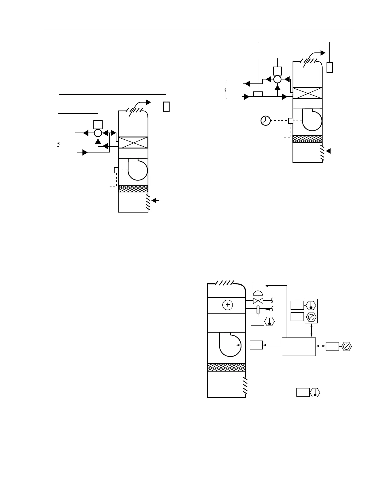
TWO-PIPE HEATING/COOLING
The flow of medium thr ough a f an coil unit can be contr olled
in two ways. One method uses a tw o-way valve to contr ol the
flow of steam or hot or c hilled water. The second method , shown
in Figure 31, uses a thr ee-way valve to contr ol hot or c hilled
water f low.
Fig. 32. Two-Pipe Heating/Cooling Fan Coil Unit.
The r oom ther mosta t opens the coil v alve on a fall in space
temper atur e dur ing the hea ting cycle. In the cooling c ycle,
chilled water in the pipes causes the pipe-mounted sensor to
reverse the ther mosta t action and the ther mosta t opens the v alve
as space temper atur e rises. The fan can be oper ated fr om a local
switch or a central time clock.
The surf ace ar ea of the coil is lar ge to accommoda te cooling
requir ements. Therefore, when a single coil is used f or both
heating and cooling , the hot w ater suppl y temper atur e should
be lower. Typical hot w ater suppl y temper atur es range between
32 and 60 °C.
Fig. 31. Two-Pipe Heating Fan Coil Unit
Using Three-Way Mixing Valve.
The thr ee-way valve provides constant f low in the suppl y
and r etur n lines and minimiz es pr essur e fluctua tions a t the v alve.
A modula ting ther mosta t contr ols the thr ee-way valve to
regulate water f low thr ough the coil. In a hea ting a pplica tion,
when the ther mosta t senses space temper atur e below the
ther mosta t setpoint, the valve is positioned to allo w full flow
thr ough the coil. As space temper atur e rises, the ther mosta t
contr ol signal modula tes the v alve to decr ease the amount of
flow thr ough the coil and incr ease the b ypass flow around the
coil. At the upper end of the ther mosta t thr ottling r ange, the
valve is in the coil b ypass position, elimina ting flow thr ough
the coil. The fan r uns contin uously or is stopped as space
temper atur e rises above setpoint. Cooling-onl y systems oper ate
in a similar w ay.
TWO-PIPE HEATING/COOLING, SINGLE COIL
Figur e 32 shows a two-pipe fan coil a pplication tha t uses a
single coil for hea ting and cooling with seasonal c hang eover.
Control for this application requires a heating/cooling room
ther mosta t tha t r everses its action fr om a r emote hea ting/cooling
chang eover signal. One method of automa tic chang eover is to
install a pipe-mounted sensor that switches thermostat action
when it senses a change in supply medium between hot and
chilled water. Because it cannot of fer sim ultaneous hea ting and
cooling capability, this system can cause pr oblems dur ing
inter media te seasons w hen hot w ater is in the system and
cooling is needed , or vice versa.
C3033
DISCHARGE
AIR
THERMOSTAT
RETURN
AIR
FILTER
HEATING
COIL
FAN
FAN
SWITCH
POWER
3-WAY
MIXING
VALVE
HOT
WATER
SUPPLY
HOT
WATER
RETURN
C3032
DISCHARGE
AIR
THERMOSTAT
RETURN
AIR
FILTER
HEATING OR
COOLING COIL
FAN
POWER
TIME
CLOCK
3-WAY
MIXING
VALVE
SUPPLY
PIPE-MOUNTED
SENSOR
RETURN
HOT
WATER
OR
CHILLED
WATER
Fig. 33. Digitally Controlled Two-Pipe
Heating/Cooling Fan Coil Unit.
M15317
FILTER
FAN
RA
OUTDOOR AIR
ON
CONTROL
PROGRAM
-1.5
24
24
8
13
77
HEATING
DEADBAND
WALL MODULE
TEMPERATURE
COOLING
SETPOINT
PERCENT
OPEN