ENGINEERING MANUAL OF AUTOMATIC CONTROL
CHILLER, BOILER, AND DISTRIBUTION SYSTEM CONTROL APPLICATIONS
318
Specification:
Condenser water temperature setpoint shall be equal to the
OA WB plus 3.5 kelvins, or the minimum temperature
acceptable to the chiller, whichever is higher. Fan shall stop
when condenser water temperature drops to setpoint. Fan shall
start at low speed when the temperature rises to the setpoint
plus 3 kelvins, and shall not stop for a minimum of 9 minutes.
Fan shall transition from low to high speed anytime it has run
at least 3 minutes at low speed and the temperature is above the
low-speed start point plus 1 kelvin or 29.5°C, whichever is
lower. Fan shall run a minimum of 9 minutes on high speed,
and shall transition from high speed to low speed if the
temperature drops to a value equal to the switch-to-high-speed
value minus 3 kelvins.
If required, use a valve control method similar to the one
used for single speed fan control.
Variable Speed Cooling Tower Fan Control
For variable speed cooling tower fans, an EPID control
function with WB optimized setpoint or fixed setpoint works
well until the fan drops to a minimum safe speed, below which
results in motor overheating. If the tower capacity is still
excessive at minimum fan speed, the fan control mode reverts
to on-off. During this mode, disable the PI function or when
the fan is restarted it will start at a speed greater than the
minimum, although the minimum speed was too great. This
produces an undesirable short on time. The following is a
possible application and specification:
SINGLE COOLING TOWER VARIABLE SPEED FAN CONTROL
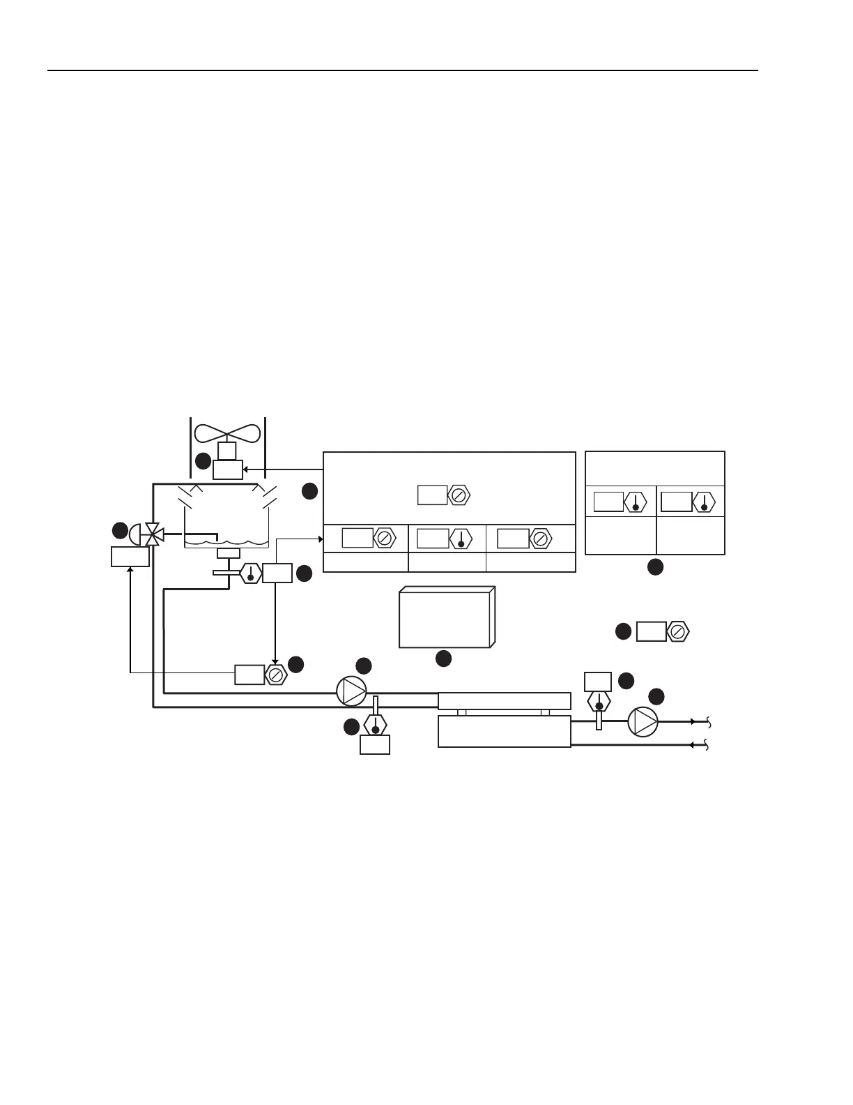
Functional Description
Fig. 29. Single Cooling Tower Variable Speed Fan Control Graphic
Item No. Function
1 Indicates percent maximum tower fan speed.
2 Sets tower minimum speed.
3 Current OA conditions.
4 Sets minimum and maximum condenser water
temperature setpoints and WB approach.
5 Icon to select tower low load control dynamic
sequence display (Fig. 30).
6 Condenser water control sensor.
7 Displays valve position.
8,9 Dynamic pump symbols denote pump
operation.
10,11 Operator information.
12 Sets valve control setpoint.
30.5 21.5
7
10
5
4
6
12
1
11
2
3
TOWER FAN CONDENSER WATER TEMPERATURE
SETPOINT EQUALS OA WET BULB TEMPERATURE PLUS
DEGREES
MINIMUM
CURRENT
MAXIMUM
DRY
BULB
WET
BULB
PERCENT
OPEN TO
TOWER
LOW LOAD/
FREEZING
CONTROL
8
9
CHILLER
PERCENT
TOWER FAN MINIMUM
SPEED EQUALS
OUTSIDE AIR
TEMPERATURE
25.5
21.5
29.5
3.5
26
77
20
7
25
100
30
M15262
 Loading...


