INDIVIDUAL ROOM CONTROL APPLICATIONS
ENGINEERING MANUAL OF AUTOMATIC CONTROL
411
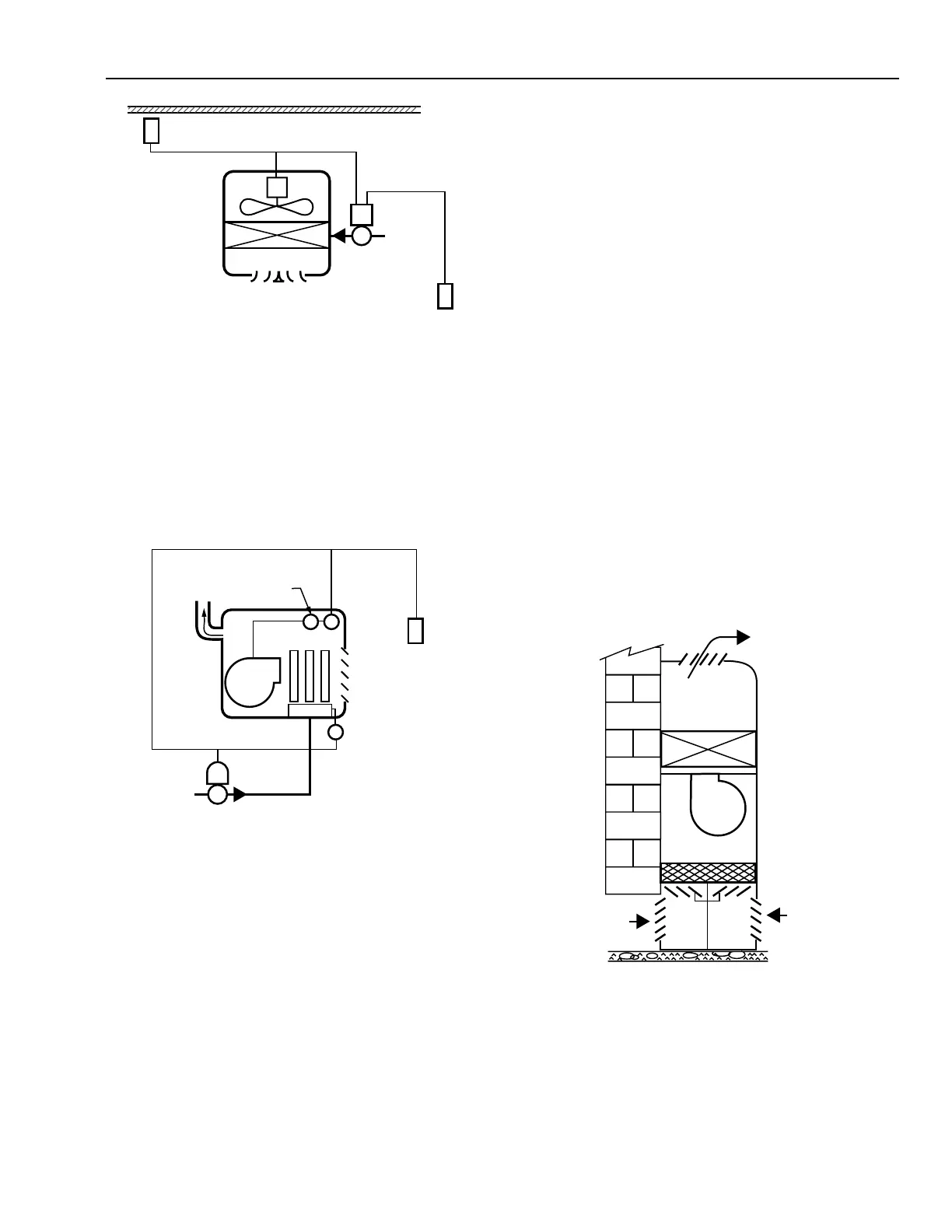
Fig. 18. Down-Blow Unit Heater.
GAS- OR OIL-FIRED UNIT HEATER
The gas-fired unit hea ter (F ig. 19) is used when a centr al hot
water or steam system is not a vailable. In a g as-fired unit hea ter,
a gas bur ner hea ts a hea t exchang er w hile a fan forces air acr oss
the exchang er to w ar m the space . The two-position contr ol
system compr ises a ther mosta t, solenoid g as valve, safety cutout
switch, pilot saf ety switch, and f an switch.
Some lar ger industr ial gas-fired unit hea ter s have two stages:
two-position (low fire) and modula ting (to high f ire). These
units are controlled by room thermostats designed to sequence
the tw o-position and modula ting sta ges on a decr ease in space
temperature.
Oil-fired unit hea ter s oper ate similar ly to gas-fired unit hea ter s
and inc lude saf ety contr ols designed f or oil bur ner s.
UNIT VENTILATORS
GENERAL
A unit v entila tor consists of damper s, a filter, a fan, a hea ting
and/or cooling coil, and the necessar y contr ols (e.g., a valve
and damper actua tor). Unit v entila tors use outdoor air ,
recirculated or return air from the space, or a mixture of both.
Unit ventila tor s ar e designed for man y capacities and ar e used
in ar eas wher e occupanc y density indica tes a need f or contr olled
ventilation (e.g., classrooms, conference rooms). A unit
ventila tor contr ol system var ies hea ting, ventila ting, and cooling
(if available) while the f an r uns contin uously.
Figure 20 shows a “blow-through” unit ventilator. Dampers
at the bottom of the unit control the amounts of outdoor air
and return air brought into the unit. The air passes through the
filter section and enters the fan section, where the fan blows it
across the coil.
CEILING
THERMOSTAT
FAN
MOTOR
COIL
DIFFUSER
DOWN-BLOW
UNIT HEATER
THERMOSTAT
C3028
VALVE
HOT WATER
OR STEAM
SUPPLY
Fig. 19. Gas-Fired Unit Heater.
When space temper atur e falls below the ther mosta t setpoint,
the ther mosta t contacts c lose to ener gize the gas valve. If the
pilot saf ety switch indica tes the pilot b ur ner is lit, the gas valve
ener gizes. The bur ner w arms the hea t exchang er and the f an
switch tur ns on the f an. The burner oper ates until space
temper atur e warms to setpoint. If unacce pta bly high
temper atur es occur in the hea ter (e .g., dur ing fan failur e), the
safety cutout s witch closes the solenoid g as valve. After the
room ther mosta t shuts of f the b ur ner, the fan contin ues to r un
until the hea t exchang er cools.
S
S S
FLUE
FAN
BURNER
HEAT
EXCHANGER
SAFETY
CUTOUT
SWITCH
THERMOSTAT
PILOT
SAFETY
SWITCH
SOLENOID
GAS VALVE
GAS
SUPPLY
FAN SWITCH
(MAY BE COMBINATION FAN
AND LIMIT CONTROLLER)
GAS-FIRED
UNIT HEATER
C3024
Fig. 20. Blow-Through Unit Ventilator.
C3037
DISCHARGE
AIR
WALL
OUTDOOR
AIR
OA, RA
DAMPERS
RETURN
AIR
FILTER
COIL
FAN