ENGINEERING MANUAL OF AUTOMATIC CONTROL
INDIVIDUAL ROOM CONTROL APPLICATIONS
406
DUAL-DUCT ATU
In a dual-duct air handling system, suppl y air is di vided a t
the centr al fan and hot air and cold air f low thr ough separ ate
ducts thr oughout the b uilding. Two of the man y DDC dual-
duct contr ol configur ations ar e included her e.
A typical or iginal dual-duct ATU dr aws hot and cold air fr om
respective ducts, mixes the air as dir ected b y a sensor in the
contr olled space , and disc har ges the mix ed air into the space .
This basic dual-duct mixing system is not economical because
air is cooled and hea ted m uch of the year. DDC systems ar e
still sometimes used with digital hot and cold duct load reset to
minimiz e the ener gy waste dur ing mixing per iods. Adapting
dual-duct systems to VAV contr ol has r esulted in signif icant
ener gy savings without discomf ort.
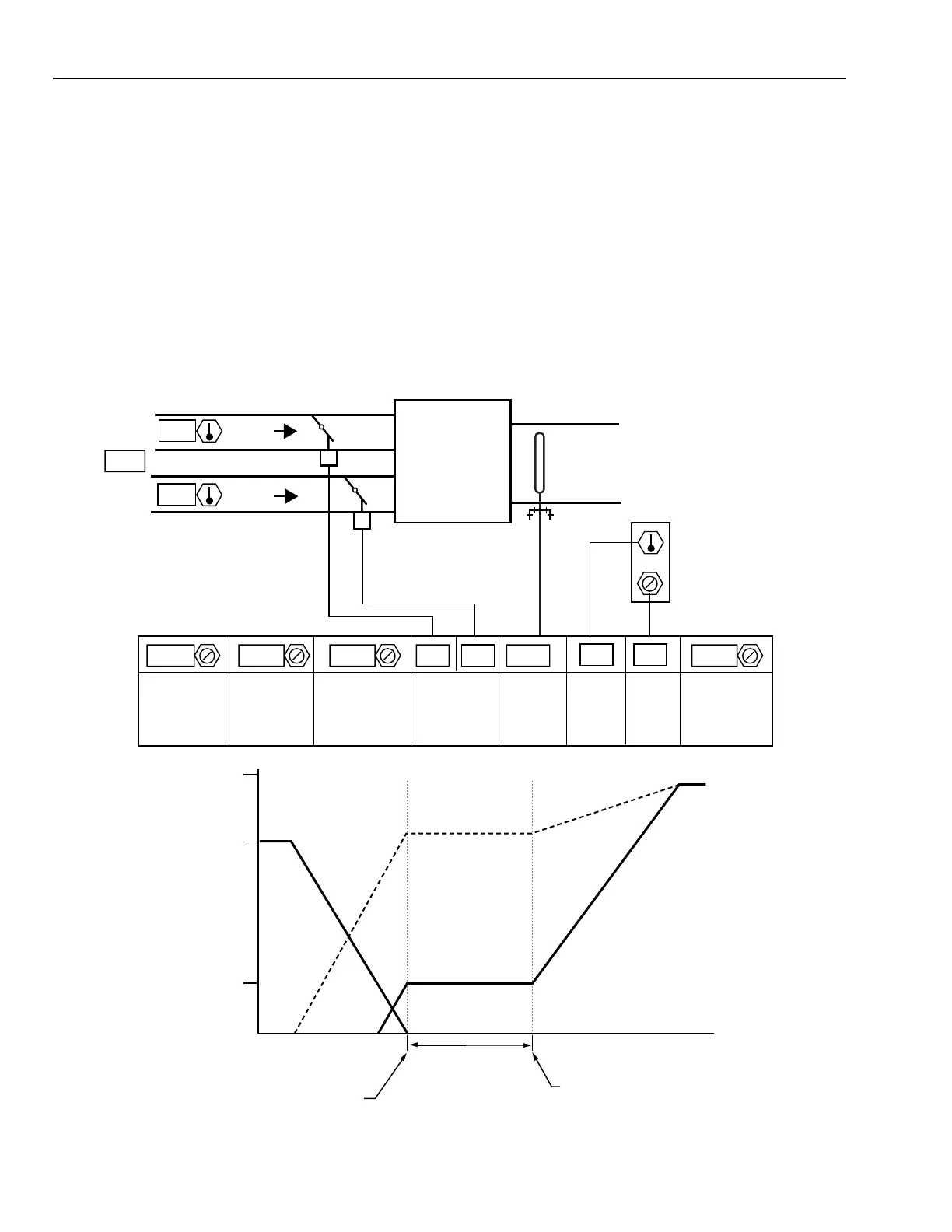
Fig. 10. Dual-Duct Pressure Independent VAV Air Terminal Unit.
Dual Duct Pressure Independent VAV ATU
Figure 10 shows a dual-duct pressure independent ATU. The
airflow sensor in the outlet of the ATU controls the cold duct
inlet damper in the cooling mode from the cooling maximum
airflow to the minimum ventilation airflow, through the dead
band, and to the heating setpoint. As the heating load increases,
the hot duct damper modulates open to control the supply
airflow from zero to the maximum heating value. This same
sequence may be achieved with two airflow elements, one in
each primary duct.
FULL
FULL
0
0
DEDBAND
(ADJUSTABLE)
M15311
HEATING
LOAD
HEATING SETPOINT
COOLING SETPOINT
COOLING
LOAD
ZERO
MIN
AIRFLOW
HEATING
MAX
COOLING
MAX
HOT DUCT
AIRFLOW
COLD DUCT
AIRFLOW
24 24
13
25.5
0.35
0.165
0.445
-1.75
0.543
0.443 00 77
MINIMUM
AIRFLOW
SETPOINT
(m
3
/s)
MAXIMUM
COOLING
AIRFLOW
SETPOINT
(m
3
/s)
kPa
CURRENT
(m
3
/s)
DAMPER
PERCENT
OPEN
HEATING
DEADBAND
COOLING
SETPOINT
TEMPERATURE
WALL MODULE
HOT
DUCT
COLD
DUCT
MAXIMUM
HEATING
AIRFLOW
SETPOINT
(m
3
/s)
 Loading...


