ENGINEERING MANUAL OF AUTOMATIC CONTROL
DAMPER SELECTION AND SIZING
463
Table 7. Pressure Drop Calculation Example.
Had the duct size been 1.50 m
2
, the same size as the damper, the pressure drop would have been lower (7.25 Pa).
MIXED AIR CONTROL
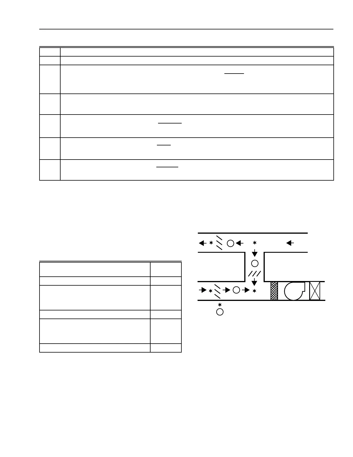
Figure 34 shows a mixed air control system. All three dampers
(outdoor, exhaust, and return air) are the primary source of
pressure drop in their individual system so parallel blade
dampers are selected to obtain linear control.
C2393
POINTS OF CONSTANT PRESSURE
RA
OA
EA
V
V
V
V
PATHS OF VARIABLE FLOW
Fig. 34. Mixed Air Control System
(Parallel Blade Dampers).
When a weather louver or bird screen is used in series with
the outdoor air and exhaust dampers (Fig. 35), the static pressure
drop shifts from the louvers/screens to the dampers as they go
from open to closed. Opposed blade dampers for outdoor air
and exhaust air provide a more linear characteristic for these
systems. The return damper is still the primary source of
pressure drop in its system so a parallel blade damper is used
to minimize pressure drop yet maintain a linear characteristic.
Control Application
Damper
Type
Return Air Parallel
Outdoor Air or Exhaust Air
(with Weather Louver or Bird Screen) Opposed
(without Weather Louver or Bird Screen) Parallel
Coil Face Opposed
Bypass
(with Perforated Baffle) Opposed
(without Perforated Baffle) Parallel
Two-Position (all applications) Parallel
DAMPER APPLICATIONS
The Table 8 indicates the damper types typically used in
common control applications.
Table 8. Damper Applications.
Step Example
1
Not applicable
2
Free area ratio (parallel blades) = (0.0798 x 1.50 m
2
)
0.1007
x
1.50 m
2
1.69 m
2
= 0.8075 x 0.8876
= 0.717
3
Pressure drop at 15.08 m/s = –3.114 x (1 – 0.717
–4.274
)
= –3.114 x –3.1449
= 9.783 Pa
4
Approach velocity =
9.45 m
3
/s
1.69 m
2
= 5.59 m/s
5
Correction factor =
25.8
5.59
2
= 0.826
6
Pressure drop across damper =
9.783 Pa
0.826
= 11.86 Pa
 Loading...


