INDIVIDUAL ROOM CONTROL APPLICATIONS
ENGINEERING MANUAL OF AUTOMATIC CONTROL
421
HEAT PUMPS
GENERAL
A heat pump is a r efrigeration system tha t pr ovides both
heating and cooling within the same unit. In the heating mode,
the pump deli vers heat fr om a hea t sour ce to the conditioned
space. In the cooling mode , the pump r emoves heat from a
space and transfers it to a heat sink. Heat pumps use standard
refrigeration components (compr essor, expansion v alve,
evapor ator, and condenser) and a r eversing valve to r everse
refrigerant f low thr ough the coils. A refrigerant r eversing valve
switches a t chang eover to con vert the condenser to an e vapor ator
and vice v ersa.
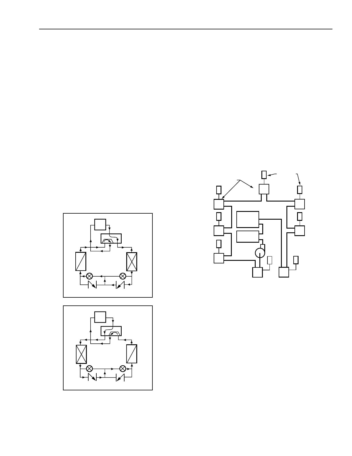
Figure 36 shows heat pump c ycles. In the cooling c ycle,
refrigerant f low uses the outdoor hea t exchang er coil as the
condenser to reject heat from the space, and the indoor coil as
the evapor ator. In the hea ting cycle, flow of air and r efrigerant
is reversed making the outdoor coil the sour ce of heat. The
indoor coil becomes the condenser and pr ovides hea t for the
space. When outdoor air temper atur es are too cold to pr ovide
enough hea t tr ansfer, electric resistance hea ting elements can
be used to pr ovide supplemental hea t. An alter native method is
to reverse indoor and outdoor airf low across the coils and
elimina te the r eversing valve.
Heat pumps ar e typicall y classified by the hea t sour ce at the
“outdoor” coil. The common air -to-air hea t pump uses outdoor
air as its hea t sour ce dur ing the hea ting cycle. A water-to-air
heat pump uses w ater as the hea t sour ce dur ing the hea ting
cycle. The water suppl y may be a well or a lak e. In the cooling
mode, the outdoor coil r ejects hea t and the air or w ater becomes
the heat sink.
In commer cial applica tions, a closed-loop or r unar ound w ater
suppl y may serve multiple units (F ig. 37). This system r elies on
load di versification. Some units ma y be cooling w hile other z ones
oper ate in the hea ting c ycle. In this case , the water loop is a sour ce
to heating units and a sink to cooling units, transferring heat from
one to the other . Water -loop temper atur es ar e maintained betw een
21°C and 32 °C to pr ovide an adequa te hea t sour ce or hea t sink. A
centr al boiler to gether with a c hiller and/or cooling to wer temper
the water in the loop dur ing peak hea ting and cooling per iods.
For a discussion of centr al r egulation and contr ol of water pump
hydr onic loops, refer to Chiller , Boiler, and Distr ibution System
Contr ol Applica tions section.
Fig. 36. Refrigerant Flow in Heat Pump
Cooling and Heating Cycles.
INDOOR
COIL
EXPANSION
VALVE FOR
HEATING
OUTDOOR
COIL
REFRIGERANT
REVERSING
VALVE
COMPRESSOR
CHECK
VALVE
HEATING CYCLE
INDOOR
COIL
EXPANSION
VALVE FOR
COOLING
OUTDOOR
COIL
REFRIGERANT
REVERSING
VALVE
COMPRESSOR
CHECK
VALVE
COOLING CYCLE
C3021
Fig. 37. Heat Pump Closed-Loop System.
OPERATION
Small and medium-sized heat pumps usually heat and cool
indoor air and ar e contr olled fr om a space ther mosta t. Lar ge
heat pumps usuall y pr ovide war m and c hilled water and ar e
contr olled by a chilled water temper atur e contr ol.
Space ther mosta ts ar e two-position and usuall y multista ge.
They typically provide automa tic changeover, switching the
heat pump between heating and cooling as required to maintain
space temper atur e. The first sta ge of the ther mosta t cycles the
compr essor. If the system is in a hea ting mode , additional
thermostat heating stages will bring on supplementary resistance
heat if the heat pump cannot meet the load. In the cooling mode,
ther e is only one sta ge that cycles the compr essor. If desir ed,
chang eover betw een hea ting and cooling can be man ual r ather
than automa tic. The ther mosta t can ha ve separ ate hea ting and
cooling settings or a single setting with a f ixed deadband
between heating and cooling.
C3022
PUMP
HEAT
PUMP
BOILER
CHILLER OR
COOLING
TOWER
THERMOSTAT
 Loading...


