ENGINEERING MANUAL OF AUTOMATIC CONTROL
DAMPER SELECTION AND SIZING
459
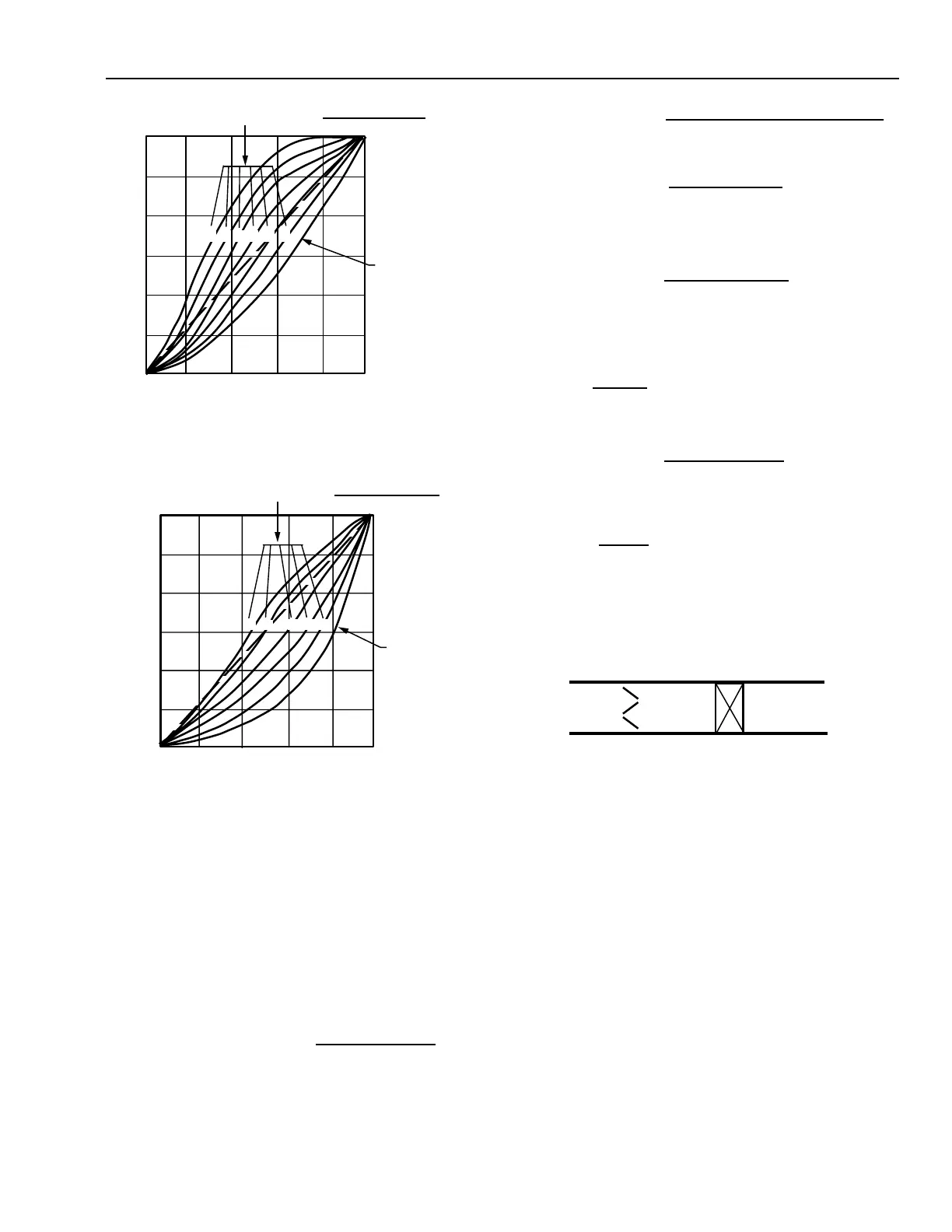
Fig. 30. Damper System Characteristics of
Opposed Blade Dampers.
To achieve performance closest to the ideal linear flow
characteristic, a characteristic ratio of 2.5 for parallel blade
dampers (Fig. 29) and 10 for opposed blade dampers (Fig. 30)
should be used. The percent of the total resistance needed by
the damper can be determined by:
Total resistance (100%) = damper resistance + series
resistance
Substituting (total resistance – damper resistance)
for series resistance:
Characteristic ratio
(Fig. 29 and 30) =
series resistance
damper resistance
Fig. 29. Damper System Characteristics of
Parallel Blade Dampers.
100
0
0
% DAMPER OPENING
% FULL AIRFLOW
C1498
100
CHARACTERISTIC RATIOS =
SERIES RESISTANCE
DAMPER RESISTANCE
INHERENT
CHARACTERISTIC
20 10 5 3 2 1
100
0
0
% DAMPER OPENING
% FULL AIRFLOW
C1499
100
CHARACTERISTIC RATIOS =
SERIES RESISTANCE
DAMPER RESISTANCE
INHERENT
CHARACTERISTIC
5 3 120 10
or
For parallel blade dampers:
Damper resistance = 29% of total resistance
or
For opposed blade dampers:
or damper resistance = 9% of total resistance
For example, if a coil (Fig. 31) with a pressure drop of 0.140 kPa
is located in series with an opposed blade damper, the damper
should have a pressure drop of 0.014 kPa (10 percent of 0.140
= 0.014).
2.5 =
100
dam
er resistance
– 1
10 =
100
dam
er resistance
– 1
9
100 – 9
= 10% of series resistance
Characteristic ratio =
total resistance – damper resistance
dam
er resistance
=
total resistance
dam
er resistance
– 1
29
100 – 29
= 41% of series resistance
Fig. 31. Typical Pressure Drop for Coil and
Damper (Series Resistance).
DETERMINING DAMPER SIZE
The desired relationship of damper resistance to series
resistance developed in DAMPER CHARACTERISTICS is
used to determine the desired damper pressure drop. This
pressure drop is then used in the damper sizing procedure in
Table 4.
For example, for a 915 mm by 1625 mm (1.487 m
2
) duct
with an airflow of 9.45 m
3
/s and a pressure drop of 0.014 kPa
across a parallel blade damper, determined the damper size as
shown in Table 5.
(Fig. 29 and 30)
0.014 kPa
DROP
0.140 kPa
DROP
M15303
 Loading...


