ENGINEERING MANUAL OF AUTOMATIC CONTROL
DAMPER SELECTION AND SIZING
460
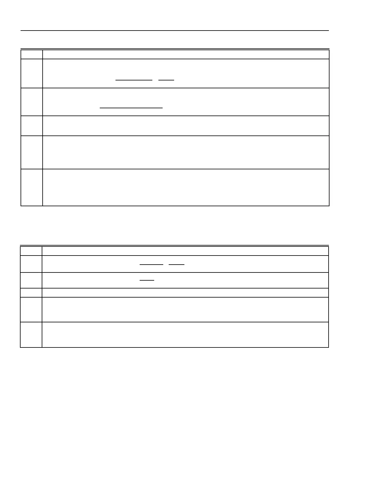
Table 4. Damper Sizing Procedure.
Table 5. Damper Sizing Example.
Step Procedure
1
Calculate the approach velocity:
Approach velocity (m/s) =
Airflow (L/s)
Duct Area (m
2
)
x
1 m
3
1000L
2
Using the approach velocity from Step 1, calculate a correction factor:
Correction factor =
25.8
[Approach velocity (m/s)]
2
3
Calculate the pressure drop at 5.08 m/s:
Pressure drop at 5.08 m/s = Pressure drop at approach velocity x correction factor (Step 2)
4
Calculate free area ratio
a
:
For pressure drops (Step 3) ≥ 57.1 Pa:
Ratio = [1 + (0.0859 x pressure drop)]
–0.3903
For pressure drops (Step 3) < 57.1 Pa:
Ratio = [1 + (0.3214 x pressure drop)]
–0.2340
5
Calculate damper area (m
2
):
For parallel blade dampers:
Damper area (m
2
) = (Duct area (m
2
) x ratio, x 1.2897)
0.9085
For opposed blade dampers:
Damper area (m
2
) = (Duct area (m
2
) x ratio, x 1.4062)
0.9217
a
The free area of a damper is the open portion of the damper through which air flows. The free area ratio is the open area
in a damper divided by the total duct area.
Step Example
1
Approach velocity (m/s) =
9440 L/s
1.485 m
2
x
1m
3
1000L
= 6.35 m/s
2
Correction factor =
25.8
16.35
= 0.64
3 Pressure drop at 5 m/s = 14.9 Pa x 0.64 = 9.43 Pa
4
Free area ratio = [1 + (0.3214 x 9.43)]
–0.2340
= 3.03
–0.2340
= 0.772
5
Damper area (parallel blades) = (1.485 m
2
x 0.772 x 1.2897)
0.9085
= 1.3828
0.9085
= 1.342 m
2
 Loading...


