PNEUMATIC CONTROL FUNDAMENTALS
ENGINEERING MANUAL OF AUTOMATIC CONTROL
83
M
MB
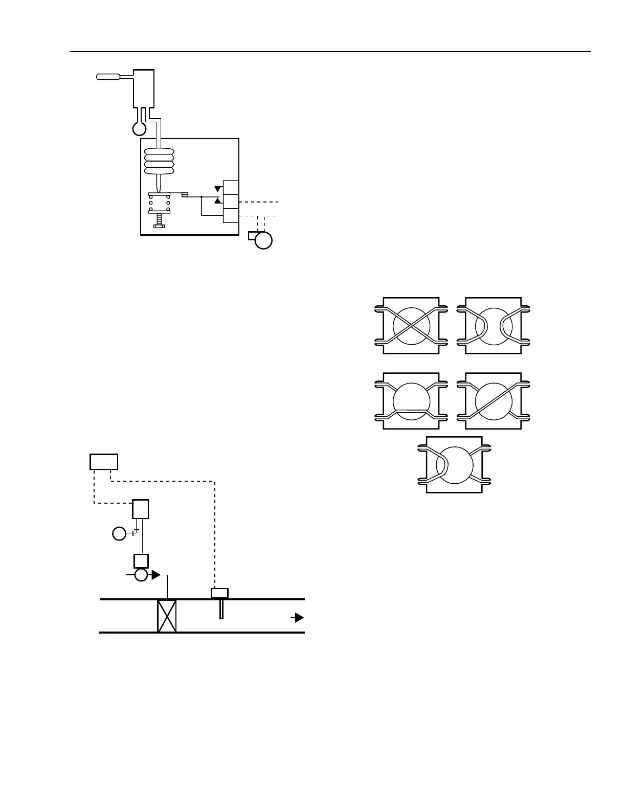
P/E RELAY
TEMPERATURE
CONTROLLER
BELLOWS
SPRING
SETPOINT
ADJUSTMENT
PUMP
PUMP
VOLTAGE
N.O.
N.C.
C
C2384
Fig. 52. P/E Relay Application.
ELECTRONIC-PNEUMATIC TRANSDUCER
The electronic-pneumatic transducer is a proportional relay
that varies the branch air pressure linearly 20 to 100 kPa in
response to changes in an electrical input of 2 to 10 volts or 4
to 20 mA. Electronic-pneumatic transducers are used as the
interface between electronic, digital, or computer-based control
systems and pneumatic output devices (e.g., actuators).
Figure 53 shows discharge air temperature control of a heating
coil using digital control for sensing and control. The output of
the transducer positions the valve on a heating coil.
M B
M
HEATING
VALVE
DISCHARGE
AIR
HEATING COIL
ELECTRONIC-
PNEUMATIC
TRANSDUCER
DDC
CONTROLLER
ELECTRONIC
TEMPERATURE
SENSOR
C2378
A resistance-type temperature sensor in the discharge air duct
is the input to the controller, which provides all of the system
adjustments and logic requirements for control. The controller
output of 2 to 10 volts dc is input to the electronic-pneumatic
transducer, which converts the signal to a 20 to 100 kPa output
to position the heating valve.
PNEUMATIC SWITCH
The pneumatic switch is available in two- or three-position
models (Fig. 54). Rotating the switch knob causes the ports to
align in one of two ways in a two-position switch, and in one
of three ways in a three-position switch. The two-position switch
is used for circuit interchange. The three-position switch
sequentially switches the common port (Port 2) to the other
ports and blocks the disconnected ports.
Fig. 53. Typical Electronic-Pneumatic
Transducer Application.
1
2
3
4
1
2
3
4
1
2
3
4
1
2
3
4
1
2
3
4
THREE-POSITION SWITCH
TWO-POSITION SWITCH
C1887
Fig. 54. Pneumatic Switches.
Figure 55 shows a typical application for sequential
switching. In the OPEN position, the valve actuator exhausts
through Port 4 and the valve opens. In the AUTO position, the
actuator connects to the thermostat and the valve is in the
automatic mode. In the CLOSED position, the actuator
connects to main air and the valve closes.