ENGINEERING MANUAL OF AUTOMATIC CONTROL
BUILDING AIRFLOW SYSTEM CONTROL APPLICATIONS
283
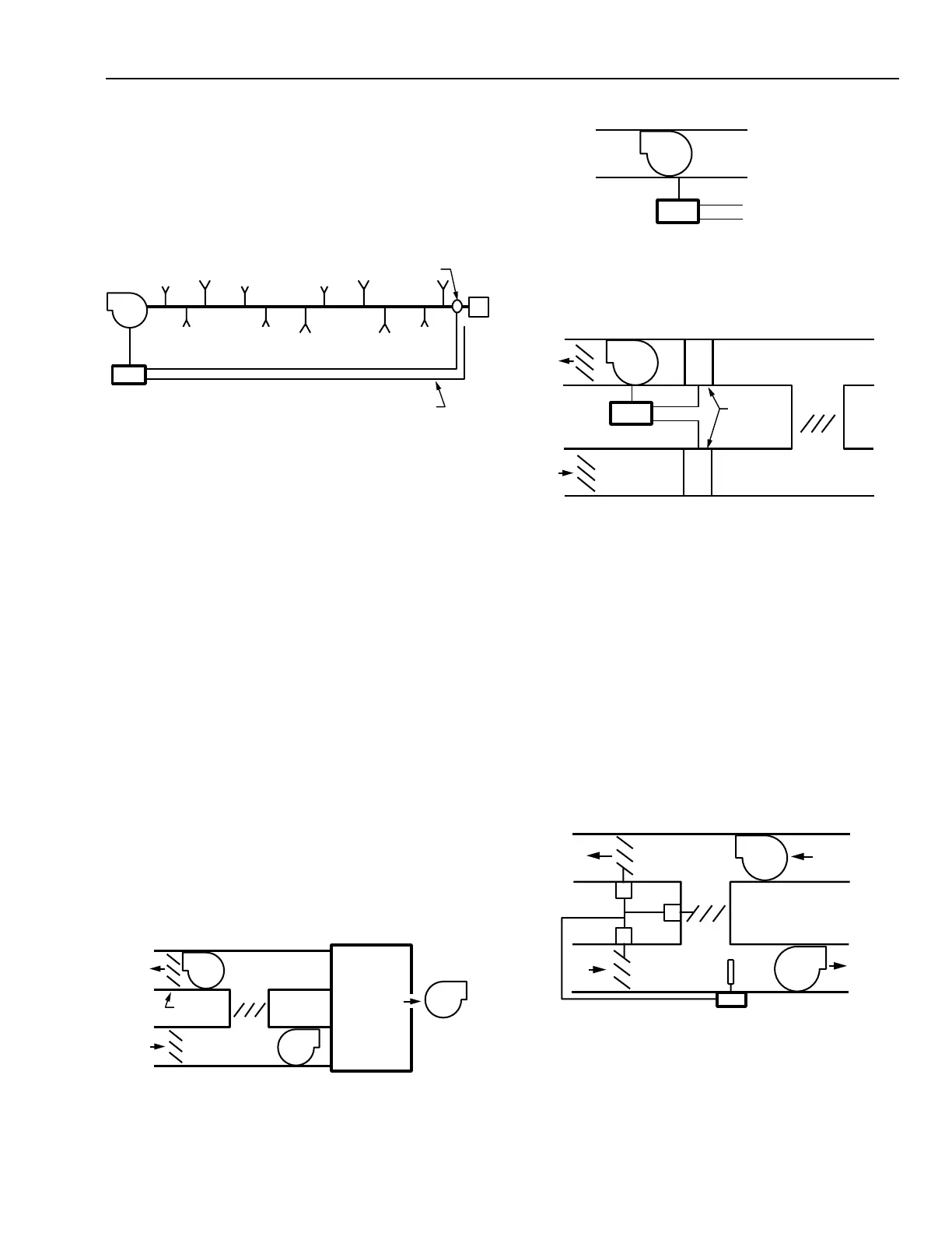
Fig. 34. Return Air Damper Mixed Air Control Cycle.
C2629
RETURN
FAN
RA
OA
RETURN
AIR
DAMPER
SUPPLY
FAN
RELIEF
DAMPER
OUTDOOR
AIR
DAMPER
MIXED AIR
TEMPERATURE
CONTROLLER
Duct Static Control
Duct static control is similar to supply fan duct static high-
limit control, except return duct static pressure is negative. If
individual space returns are damper controlled, return fan
control must use this technique (Fig. 30). Duct static control is
relatively simple, but individual space return controls make the
entire system complex.
C2625
DUCT STATIC
PRESSURE SENSOR
STATIC PRESSURE
REFERENCE
RETURN
FAN
CONTROLLER
Fig. 30. Duct Static Control.
Minimum building outdoor air is the difference between
supply total airflow and return total plus the exhaust fan total
airflow. If controlling the space returns from airflow tracking
(using dampers), the exhaust fan volume must be included in
the tracking control system for constant building and space
pressurization. If controlling the space returns by space
pressurization, building and space pressurization remain
constant regardless of exhaust fan operation.
RELIEF FAN CONTROL FOR VAV SYSTEMS
Relief fans are exhaust fans for the central air handling
system. They relieve excessive building pressurization and
provide return air removal for economizer cycles.
In Figure 31, a relief damper is located after the relief fan
and is controlled to open fully whenever the relief fan operates.
Direct building static pressure or airflow tracking controls the
relief fan. In direct building static pressure control (Fig. 32),
the same guidelines apply as for return fan control. During
minimum ventilation cycles and when the outdoor air damper
is closed, the relief fan should be turned off and the relief damper
closed. In airflow tracking (Fig. 33), flow measuring stations
should be located in relief and outdoor air ducts, not in supply
and return ducts as with return fans.
RELIEF
FAN
SUPPLY
FAN
BUILDING
SPACE
EXHAUST
FAN
C2626
OA
RA
RELIEF
DAMPER
RELIEF
FAN
STATIC PRESSURE
CONTROLLER
BUILDING SPACE
STATIC PRESSURE
OUTDOOR STATIC
PRESSURE
C2627
C2628
AIRFLOW
CONTROLLER
FLOW
MEASURING
STATIONS
RELIEF
FAN
OA
RA
Fig. 31. Relief Damper Location.
Fig. 33. Airflow Tracking Control for Relief Fan.
RETURN DAMPER CONTROL FOR VAV SYSTEMS
In systems having a return fan, when the mixed air control
cycle is not operating, the outdoor air (or maximum outdoor
air) and relief dampers are closed and the return damper remains
fully open. When the mixed air control cycle is operating, the
return damper modulates closed and outdoor air (or maximum
outdoor air) and relief dampers modulate open. The return
damper should be sized for twice the pressure drop of the
outdoor air (or maximum outdoor air) and relief dampers. This
prevents the possibility of drawing outdoor air through the relief
damper (Fig. 34).
Fig. 32. Direct Building Static Control for Relief Fan.