ENGINEERING MANUAL OF AUTOMATIC CONTROL
AIR HANDLING SYSTEM CONTROL APPLICATIONS
225
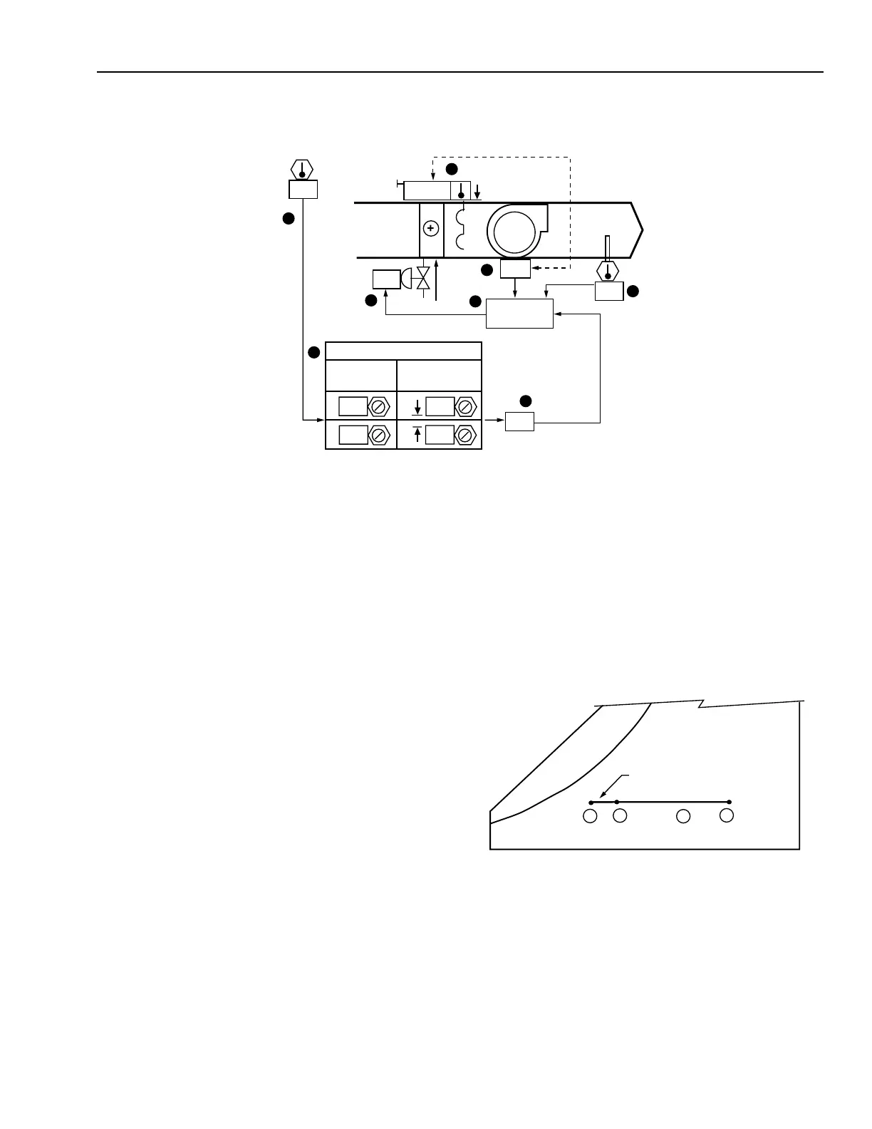
OUTDOOR AIR TEMPERATURE RESET OF SUPPLY AIR TEMPERATURE
Functional Description
Item
No. Function
1,2 Control system energizes when fan is turned on
(See FAN SYSTEM START-STOP CONTROL).
3,4 SA temperature setpoint, as adjusted by reset
schedule, maintained by modulating hot
water valve.
5,6 OA temperature resets the SA temperature setpoint
according to a reset schedule.
7 Hot water valve modulates flow, opens upon loss
of motive force, and closes upon fan shutdown.
8 Control program coordinates SA temperature,
valve, and fan interlock control.
FEATURES
The SA temperature rises as the OA temperature falls
according to a predetermined reset schedule.
CONDITIONS FOR SUCCESSFUL OPERATION
Use multiple inline coil arrangement should be used if a high
temperature rise is required.
SPECIFICATIONS
See FAN SYSTEM START-STOP CONTROL.
Anytime the supply fan runs, heating control shall be enabled.
A SA PID control loop shall modulate the hot water valve to
maintain the SA temperature setpoint. The SA temperature
setpoint shall be reset from 16°C to 38°C as the OA temperature
varies from 16°C to –15°C.
PSYCHROMETRIC ASPECTS
The SA condition depends on the entering air condition and
the temperature rise needed to satisfy the space heating
requirements.
In the following chart it is assumed that:
1. The MA system is set to maintain 16°C DB MA
temperature.
2. The OA temperature reset controller increases the
setpoint of the discharge PID control loop linearly from
16°C to 38°C DB as OA temperature falls from 16°C to
–15°C DB.
2
1
4
3
ENTERING
AIR
C2550-2
The following results are obtained:
Item
No. Explanation
1 MA temperature.
2 SA at the beginning of the reset schedule.
3 SA heated to 38°C at outdoor design
temperature.
4 Between –18°C and 16°C OA temperature,
SA temperatures are between Points 2 and 3.
M15161
8
CONTROL
PROGRAM
SA
OA
MA
ON
1
3
2
6
4
24
16
23
NORMAL
38
16
RESET SCHEDULE
SETPOINT
OUTDOOR
AIR
SUPPLY AIR
SETPOINT
16
-15
7
5
00
 Loading...


