ELECTRIC CONTROL FUNDAMENTALS
ENGINEERING MANUAL OF AUTOMATIC CONTROL
101
CONTROLLER
L1 L2
LIMIT
SWITCH
ACTUATOR
LINE
VOLTAGE
C2506-1
MOTOR
DRIVE
SHAFT
CAM
SOLENOID
BRAKE
T1 T2
L1 L2
LINE-VOLTAGE
CONTROLLER
ACTUATOR
C2507
C2508
THERMOSTAT
FAN
MOTOR
LOW-LIMIT
CONTROLLER
LINE VOLTAGE
C2509
THERMOSTAT
ACTUATOR
HOT WATER
SUPPLY
HIGH-LIMIT
CONTROLLER
LINE VOLTAGE
L1
L2
TO
COIL
VALVE
Fig. 5. Series 40 Actuator Circuit
with Line-Voltage Motor.
Most Series 40 actuators have low-voltage motor coils and a
built-in line-voltage to low-voltage transformer. Power to the
unit is line voltage but the control circuit in the motor is normally
low voltage. These actuators can use either a Series 40 line-
voltage controller or a Series 80 low-voltage controller and are
wired as shown in Figure 4. Series 40 controllers can also be
used in the line-voltage supply to the actuator.
Some Series 40 actuators have line-voltage motor coils and
can use either a Series 40 line-voltage controller or a Series 60
two-position controller (which is also line voltage) and are wired
as shown in Figure 5.
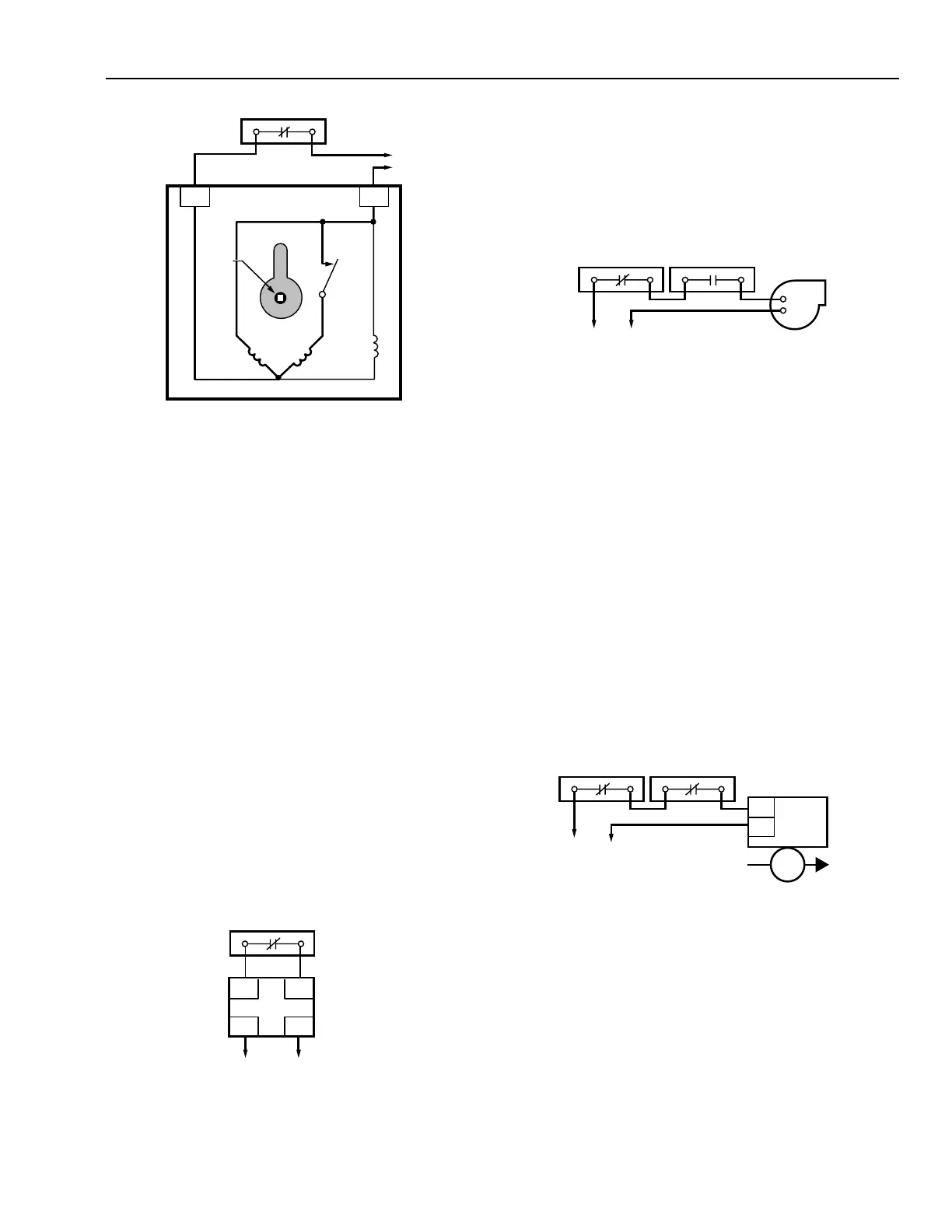
OPERATION
A simple Series 40 circuit is shown in Figure 6. It consists of:
1. A Series 40 (or 80) controller.
2. A Series 40 actuator with low-voltage control circuit.
When the controller switch is closed as in Figure 6, the
actuator drives to the open limit where it is held by the solenoid
brake. When the controller switch is open, the actuator returns
to its spring-return position. Series 80 controllers cannot be
used with actuators having a line-voltage control circuit.
Fig. 6. Series 40 Control Circuit.
CONTROL COMBINATIONS
UNIT HEATER CONTROL
In unit heater control (Fig. 7) it is usually necessary to keep
the heater fan from running to prevent circulation of cold air
when heat is not being supplied to the heater coils.
Fig. 7. Series 40 Unit Heater Control System.
The thermostat controls the fan motor from room temperature.
The low-limit controller is a reverse-acting temperature controller
installed with the sensing element in the steam or water return
from the unit heater. It is connected in series with the thermostat
and fan motor and prevents the fan from operating until the
medium flow is established through the coil. With large fan motors,
a relay must be added to handle the motor load.
HIGH-LIMIT CONTROL
Figure 8 shows a Series 40 thermostat and a high-limit
controller operating a hot water valve. The thermostat controls
the hot water valve from room temperature. The high-limit
controller is located in the discharge of the heating coil to
prevent excessive discharge air temperatures. The high-limit
controller is wired in series with the thermostat and valve so
that it opens the circuit to the valve on a rise in discharge
temperature to the high-limit setting.
Fig. 8. Series 40 Control System with High Limit.