PNEUMATIC CONTROL FUNDAMENTALS
ENGINEERING MANUAL OF AUTOMATIC CONTROL
77
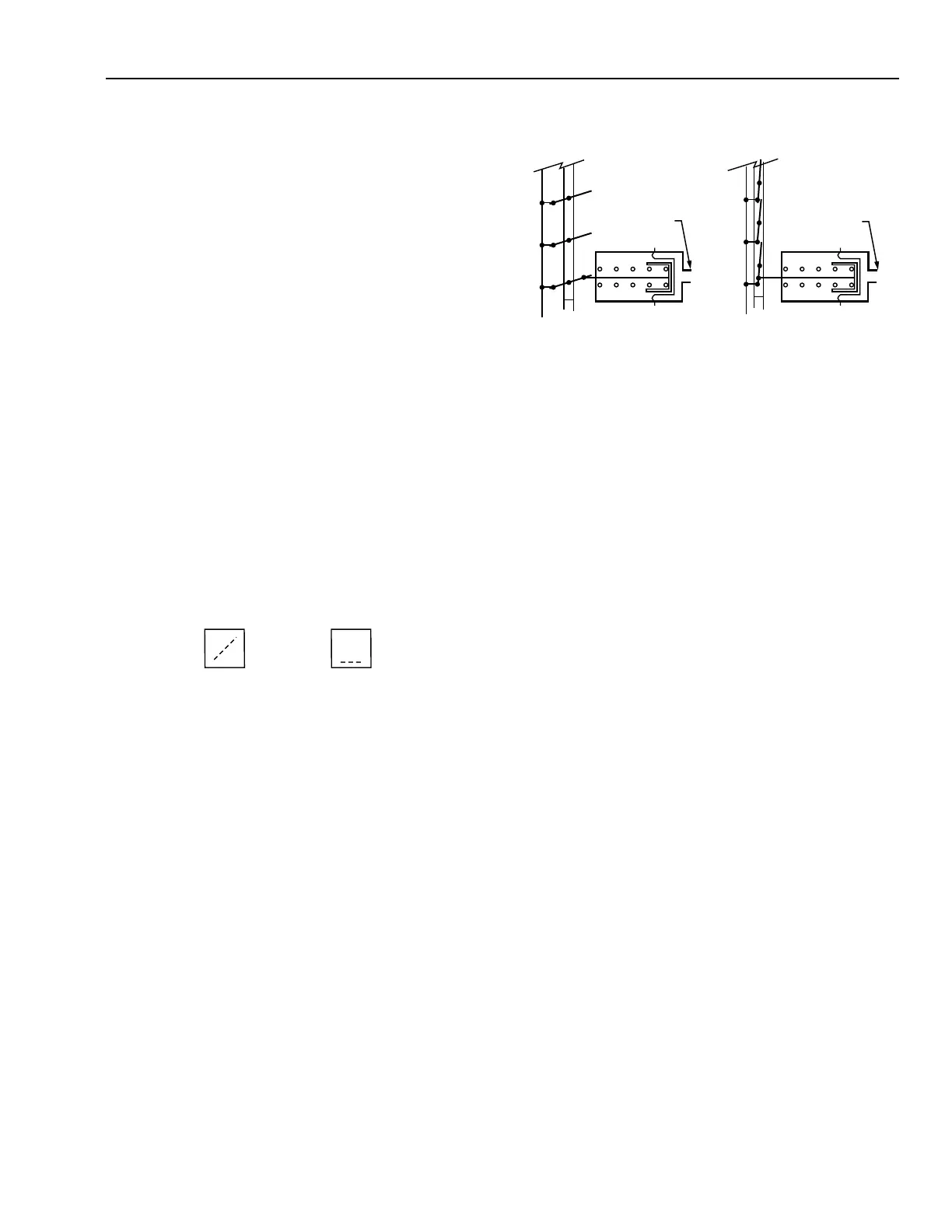
Figure 33 shows normally open and normally closed paral-
lel-blade dampers. A normally open damper returns to the open
position with low air pressure in the actuator diaphragm
chamber. An increase in branchline pressure forces the rolling
diaphragm piston to move against the spring, and a decrease
allows the compressed spring to force the piston and diaphragm
back to the normal position. As with valve actuators, interme-
diate positions depend on a balance between the force of the
control air pressure on the diaphragm and the opposing force
of the actuator spring.
A normally closed damper returns to the closed position with
low air pressure in the actuator diaphragm chamber. The way
the damper blades, crank arm, and push rod are oriented during
installation determines the normal (open or closed) position of
the damper blades.
For a more detailed discussion of dampers, see the Damper
Selection and Sizing section.
PILOT SIGNAL BELOW
RELAY SETPOINT
PILOT SIGNAL ABOVE
RELAY SETPOINT
PORTS: P= PILOT
C= COMMON
O= NORMALLY CONNECTED
X= NORMALLY DISCONNECTED
C2344
PO
CX
PO
CX
C2605
NORMALLY OPEN
DAMPER ASSEMBLY
BRANCH LINE
BRANCH LINE
ACTUATOR
NORMALLY CLOSED
DAMPER ASSEMBLY
ACTUATOR
RELAYS AND SWITCHES
In the following illustrations, common (C) and the normally
connected port (O) are connected on a fall in pilot pressure (P)
below the relay setpoint, and the normally disconnected port
(X) is blocked (Fig. 34). On a rise in pilot pressure above the
relay setpoint, C and X are connected and O is blocked.
Fig. 34. Relay Port Connections.
SWITCHING RELAY
A switching relay requires a two-position pilot signal and is
available with either single-pole, double-throw (spdt) or double-
pole, double-throw (dpdt) switching action. Pneumatic heating
and cooling control systems use relays to switch a valve or
damper actuator from one circuit to another or to positively
open or close a device. Both spdt and dpdt switching relays are
available with a variety of switching pressures.
Figure 35 shows a typical spdt switching relay application for
heating/cooling operation in which the thermostat controls the
heating/cooling coil valve. Seasonal mainline pressure changes
cause the action of the thermostat to be reversed. A discharge
low-limit control is switched into the control circuit for heat-
ing and out of the circuit for cooling. The switching is done
from mainline pressure connected to the pilot port (P).
During the heating cycle, the 124 kPa mainline pressure is
above the preset switching pressure. The common port (C)
connects to the normally disconnected port (X), connecting the
low-limit controller to the thermostat branchline to prevent
discharge temperatures below the controller setting. The
normally connected port (O) is blocked.
Fig. 33. Normally Open and Normally Closed Dampers.