ENGINEERING MANUAL OF AUTOMATIC CONTROL
AIR HANDLING SYSTEM CONTROL APPLICATIONS
223
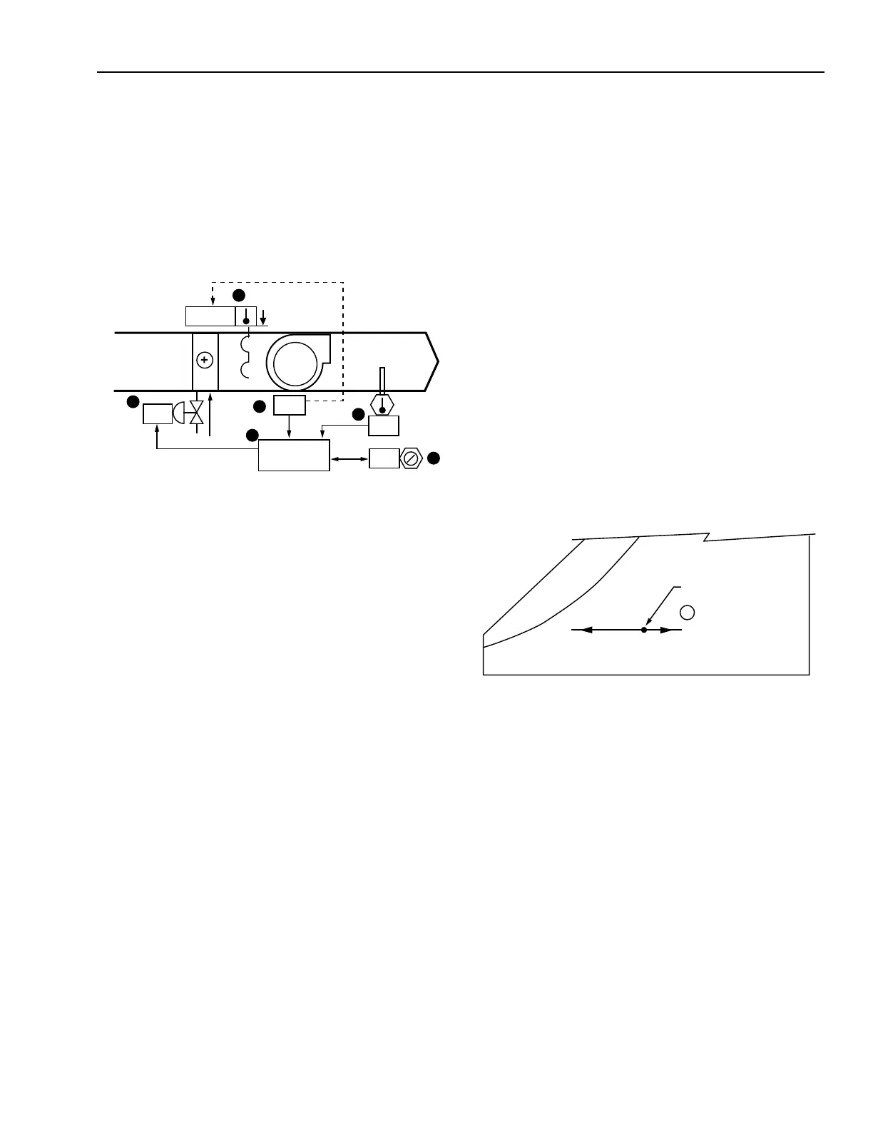
HEATING CONTROL PROCESSES
Item
No. Function
1-2 Control system energizes when fan is turned
on (See FAN SYSTEM START-STOP
CONTROL).
3,5 SA temperature maintained by modulating the
hot water valve.
4 Setpoint for SA temperature control.
6 Control program coordinates temperature
control and fan interlock.
FEATURES
1. Air is discharged at a minimum temperature.
2. Valve opens upon loss of motive force (electricity or
compressed air) and closes upon fan shutdown.
CONDITIONS FOR SUCCESSFUL OPERATION
1. A multiple inline coil arrangement should be used if a
high temperature rise is required.
2. Heating medium and flow must be available.
SPECIFICATIONS
See FAN SYSTEM START-STOP CONTROL.
Anytime the supply fan runs, the hot water valve shall be
modulated by an SA PID control loop to maintain the SA
temperature setpoint. The hot water valve shall close upon fan
shutdown and open upon loss of motive force.
PSYCHROMETRIC ASPECTS
1. The SA temperature remains constant until the entering
air temperature exceeds the desired SA temperature.
2. In the following chart it is assumed that the SA PID
control loop is set at 24°C.
The following results are obtained:
Item
No. Explanation
1 Coil discharge is 24°C DB until MA exceeds
24°C DB, above which the coil valve is
closed, no heat is added, and SA condition is
equal to MA.
The following applications show various ways to control
heating in an air conditioning system.
CONTROL FROM SUPPLY AIR
Functional Description
C3238
24°C COIL DISCHARGE
CONTROLLER SETPOINT
MA
1
M15159
6
CONTROL
PROGRAM
SA
N.O.
MA
ON
5
1
3
4
2
00
24
NORMAL
24
PERCENT
OPEN