ENGINEERING MANUAL OF AUTOMATIC CONTROL
CHILLER, BOILER, AND DISTRIBUTION SYSTEM CONTROL APPLICATIONS
332
MULTIPLE BOILER SYSTEMS
GENERAL
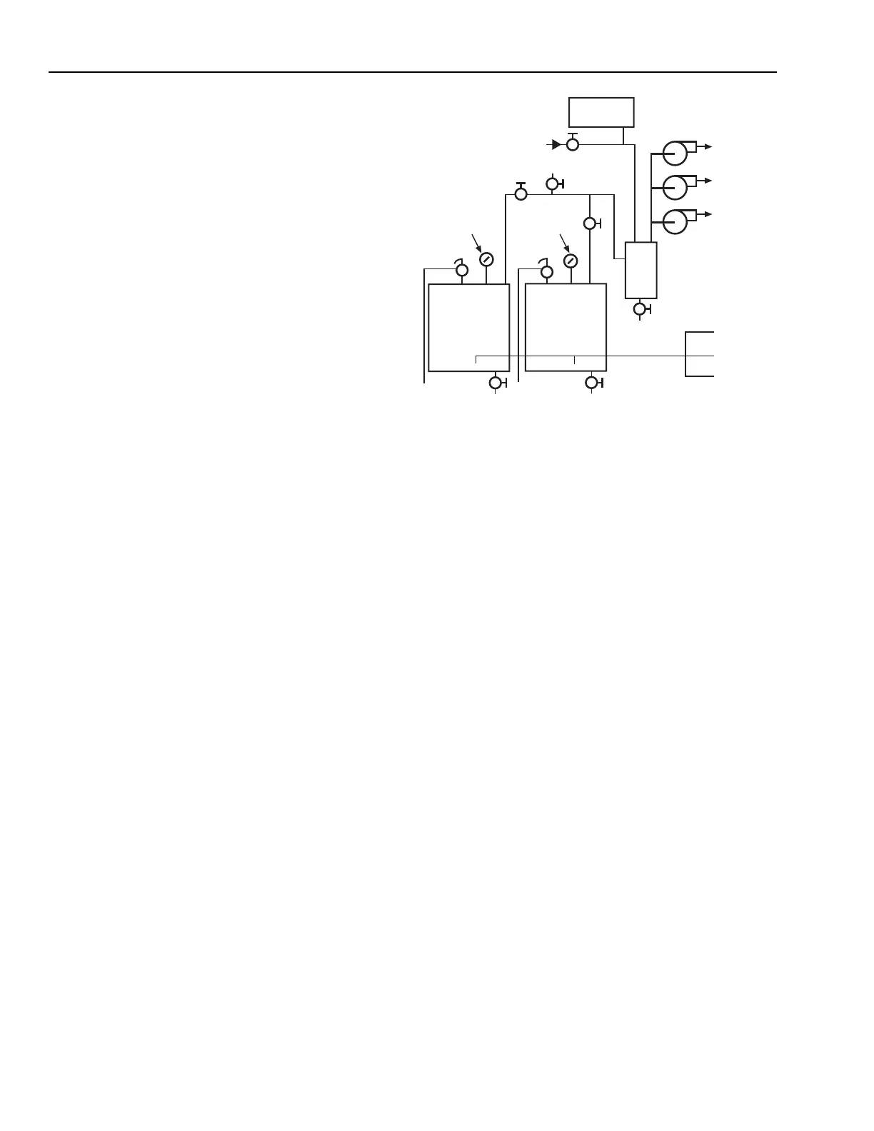
Basic boiler connections for a three-zone hot water system
are shown in Figure 47. In this system, two boilers are connected
in parallel. Hot water from the top of the boilers moves to the
air separator which removes any entrapped air from the water.
The expansion tank connected to the separator maintains
pressure on the system. The tank is about half full of water
under normal operating conditions. Air pressure in the tank
keeps the system pressurized and allows the water to expand
and contract as system water temperature varies. Water from
the boiler moves through the separator to the three zone pumps,
each of which is controlled by its own zone thermostat. In some
systems, each zone may have a central pump and a valve. Return
water from the zones returns to the boiler in the return line.
There several variations are possible with this type system but
the process is the same. There is no minimum boiler water flow
limit in this example.
The Dual Boiler Plant Control example following is a dual
boiler plant with high-fire, low-fire controlled boilers, 63°C
minimum entering water temperature required prior to high-
fire, water flow must be maintained when the boiler is enabled,
and a secondary hot water reset schedule of 43°C water at 13°C
OA temperature and 82°C water at –15°C OA temperature. The
concepts adapt well for single or multiple boiler systems.
Fig. 47. Typical Piping for Multiple-Zone
Heating System.
NOTE: The primary/secondary decoupler is sized for the full
secondary flow, and like the chiller plant decoupler,
should be a minimum of 6 pipe diameters in length.
Unlike the chiller decoupler, normal flow may be in
either direction.
EXPANSION
TANK
MAKE-UP
WATER
MANUAL
AIR VENT
PRESSURE
GAUGE
RELIEF
VALVE
PRESSURE
GAUGE
RELIEF
VALVE
BOILER
BOILER
DRAIN
DRAIN
DRAIN
AIR
SEPERATOR
ZONE
HWS
ZONE
HWR
ZONE
HWR
ZONE
HWR
ZONE
HWS
ZONE
HWS
C2905
RETURN
LINE