ENGINEERING MANUAL OF AUTOMATIC CONTROL
CHILLER, BOILER, AND DISTRIBUTION SYSTEM CONTROL APPLICATIONS
311
Fig. 18. Digital control of Sequenced Cooling Towers.
Multiple Centrifugal Chiller Sequencing
FUNCTIONAL DESCRIPTION
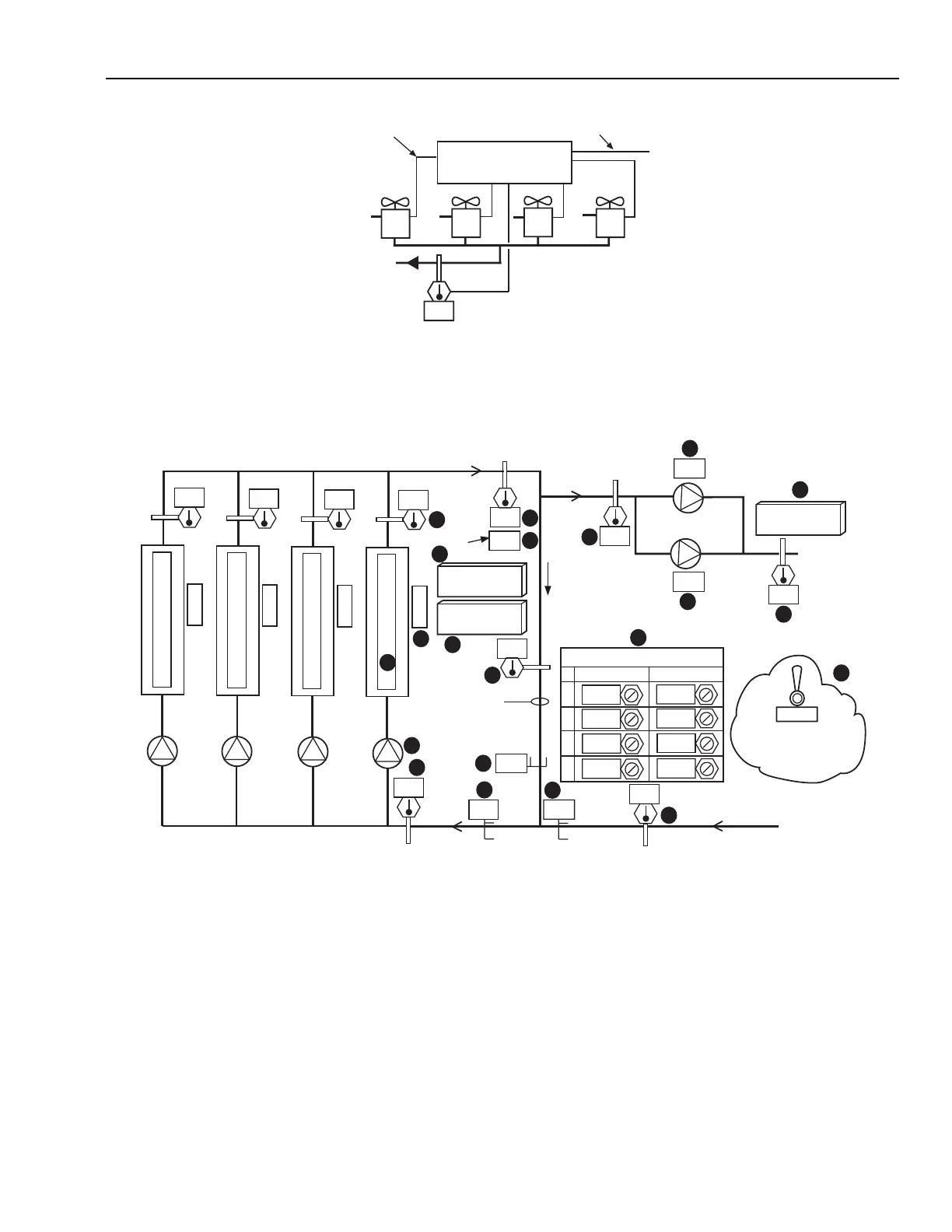
Fig. 19. Control Graphic for Multiple Similar Chillers.
Item No. Function
1,2 Secondary pump speeds.
3 Icon for selection of secondary control details.
4 Secondary pump leaving water temperature
(operator information).
5 Four chiller pump status indicators (green = on,
yellow = off, red = alarm) (typical).
6 Four Icons for selection of chiller detail graphic.
7 Four chiller status indicators (typical), operator
information.
8 BMCS commandable AUTO-OFF functions for
each chiller and ON-OFF-AUTO functions for each
chiller pump.
9 Decoupler temperature—indicates direction of flow.
10 Primary flow—indicates primary loop loading.
11 Secondary flow—indicates secondary loop loading.
12 Decoupler flow the difference between primary and
secondary flows.
13-16 Temperatures for calculating secondary flow.
17 Status of optional AUTO-MANUAL toggle switch.
18 Four chiller CHWS temperature indicators.
19 Operator information (from secondary system).
20 Icon for selection of chilled water setpoint details
display.
21 Icon for selection of chiller sequencing display
(Fig. 20).
29.5
CT
4
CT
3
CT
2
CT
1
COOLING TOWER
STAGING & LOADING
CONTROLLER
COMMUNICATION WITH
CONDENSER PUMP/ CHILLER
CONTROLLERS
FAN AND TOWER ISOLATION
VALVE CONTROL (TYPICAL)
M15259
SETPOINT
CONTROL
PUMPS
CHILLERS
102
102
7.0
T
SP4
C
H
I
L
L
E
R
4
O
F
F
7.0
T
SP3
C
H
I
L
L
E
R
3
O
N
7.0
T
SP2
C
H
I
L
L
E
R
2
O
F
F
7.0
T
SP1
C
H
I
L
L
E
R
1
O
N
P
P4
P
P3
P
P2
P
P1
12.5
7.0
7.0
7.0
0
13.0
PLANT CONTROL
1
2
3
4
AUTO
SYSTEM
AUTO-MANUAL
SWITCH STATUS
OPTIONAL
Y
G
Y
G
FS
L/s
T
RS
FP
L/s
T
D
T
SP
CHILLER
SEQUENCING
SETPOINT
T
SS
P
S2
T
SS
12.8
AUTO
AUTO
AUTO
AUTO
AUTO
AUTO
AUTO
AUTO
74
% SPEED
% SPEED
SECONDARY
SYSTEM
7.0
L/s
PC
T
RP
DECOUPLER
LINE
7.4
13
10
12
11
15
9
21
6
14
19
16
2
4
1
3
17
8
18
5
7
20
M15260