ENGINEERING MANUAL OF AUTOMATIC CONTROL
CHILLER, BOILER, AND DISTRIBUTION SYSTEM CONTROL APPLICATIONS
337
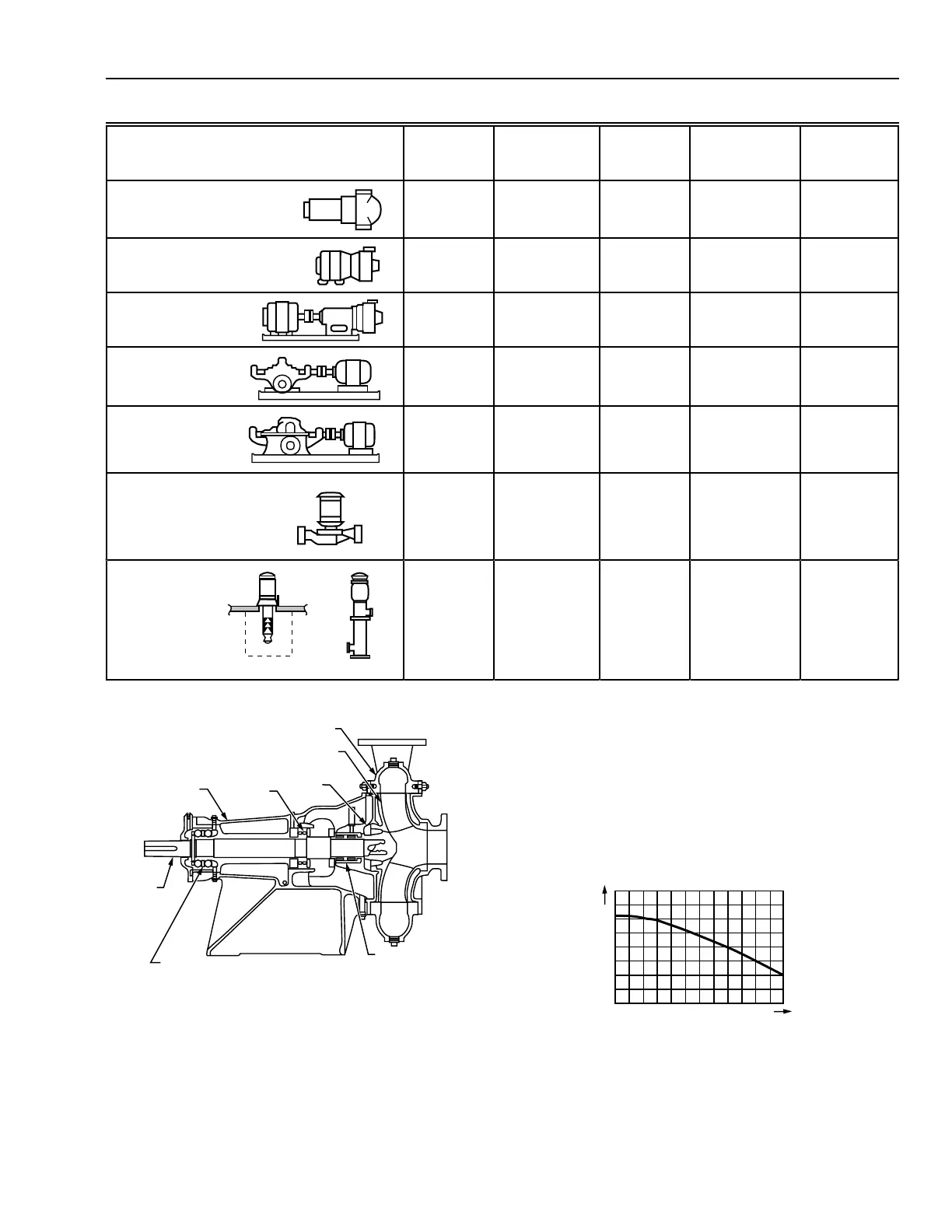
Table 2. Characteristics of Centrifugal Pump Types.
Type
Impeller
Type
No. of
Impellers Casing
Motor
Connection
Motor
Mounting
Position
Circulator
Single
suction
One Volute Flexible-
coupled
Horizontal
Close-coupled,
end suction
Single
suction
One or two Volute Close-
coupled
Horizontal
Frame-mounted,
end suction
Single
suction
One or two Volute Flexible-
coupled
Horizontal
Double suction,
horizontal
split case
Double
suction
One Volute Flexible-
coupled
Horizontal
Horizontal split
case,
multistage
Single
suction
Two to five Volute Flexible-
coupled
Horizontal
Vertical inline
Single
suction
One Volute Flexible- or
close-
coupled
Vertical
Vertical
turbine
Single
suction
One to twenty Diffuser Flexible-
coupled
Vertical
Source: ASHRAE Handbook—1996 Systems and Equipment
Fig. 52. Typical Cross-Section of an End Suction Pump.
PUMP PERFORMANCE
The performance of a given pump is expressed in a curve
showing pump pressure versus flow. Figure 53 shows a typical
curve. The pump pressure is expressed in kilopascals which
describes pump operation independent of water temperature or
density. Pressure losses in piping and components used in HVAC
systems are always calculated in kilopascals.
FRAME
INBOARD
BEARING
IMPELLER
RING
IMPELLER
CASING
ROTATING
ELEMENT
MECHANICAL
SEAL
OUTBOARD
BEARING
PUMP
SHAFT
M10509
OUTLET
INLET
Fig. 53. Typical Pump Pressure Capacity Curve.
C2907
FLOW
INC
TOTAL HEAD
INC