ENGINEERING MANUAL OF AUTOMATIC CONTROL
DAMPER SELECTION AND SIZING
451
MULTIPLE SECTION DAMPERS
Typically, single rectangular dampers are manufactured in
incremental sizes, up to maximum horizontal and vertical limits.
If system requirements dictate damper sizes larger than the
maximum available, single dampers can be arranged in multiple
section assemblies (Fig. 13).
M10417
Fig. 13. Multiple Section Damper Assembly.
Multiple section damper assemblies have the drive blades
interconnected between sections so all the sections operate in
unison. Figures 14 and 15 show methods of connecting drive
blades and cross-connecting damper blade linkage for a multiple
section damper. As a multiple section damper assembly
increases in size, additional precautions are required to
withstand pressure drop forces, including:
— Increased bracing at intersecting corners of individual
dampers.
— Additional external supports from the damper frame near
the center of the assembly to other solid structural
members adjacent to the assembly.
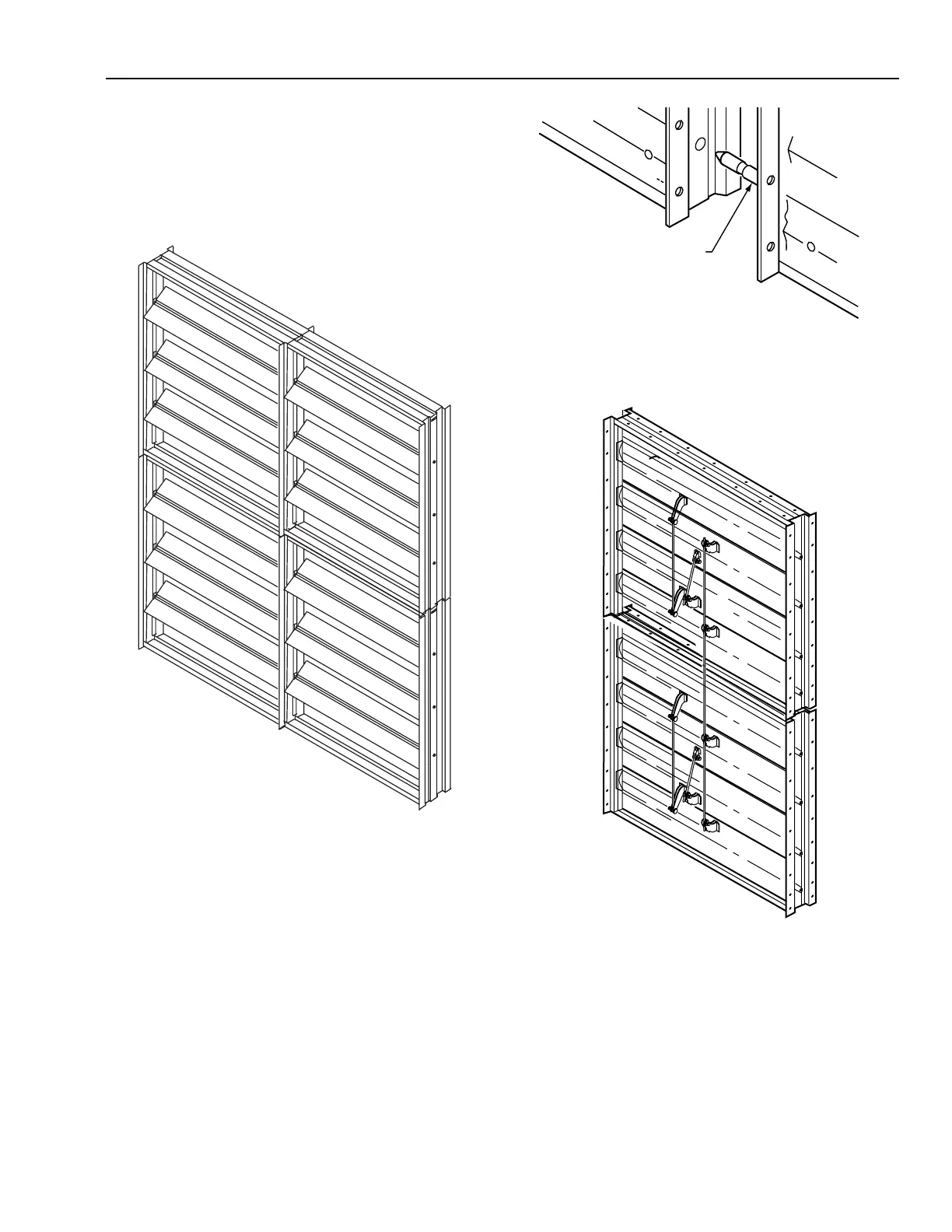
Fig. 14. Drive Blade Axle Extended for Horizontal
Multiple Section Damper Assembly.
DRIVE
BLADE
AXLE
M10410
DRIVE
BLADE
DRIVE
BLADE
Fig. 15. Drive Blade Linkage for Vertical
Multiple Section Damper Assembly.
BAFFLES
System duct sizes do not always correspond with the available
sizes of a damper or multiple section damper assembly. In these
cases, a baffle is used inside the duct to surround the damper
(Fig. 16).