ENGINEERING MANUAL OF AUTOMATIC CONTROL
CHILLER, BOILER, AND DISTRIBUTION SYSTEM CONTROL APPLICATIONS
377
C2583
INSTANTANEOUS
CONVERTER
PUMP
OA
DAMPER
ACTUATOR
OA
N.C.
PREHEAT OR
TEMPERING
COIL
LOW TEMP CONTROLLER
TO SHUT DOWN FAN
FAN
TEMPERATURE
CONTROLLER
TEMPERATURE
CONTROLLER
HIGH LIMIT
FOR CONVERTER
(CLOSES VALVE ON
TEMP. RISE)
EXPANSION
TANK
HTWS HTWR
VALVE
RELAY-
CLOSES
VALVE WHEN
FAN STOPS
POWER
FROM
FAN
CIRCUIT
RELAY-CLOSES OA DAMPER
ON FAN SHUTDOWN
A constant temperature hot water supply is used where a
minimum temperature is required for all or part of the converter
load. Normally a converter for space heating does not require
fast response as the load changes only as fast as occupancy and
outdoor air conditions change. Because of the inherent fast
converter response there are several control requirements:
1. The primary sensing element must be located in outlet
water as close to the converter as possible.
2. A stainless steel well that matches the element with heat
conductive compound in the well must be used.
3. A primary control must be used that has integral action
and integral cutout to allow a wider throttling range for
stability with minimum deviation from setpoint and to
eliminate integral windup.
A control arrangement for a typical zone supplied with HW
from a HTW to constant temperature HW converter is shown
in Figure 119. Water temperature in the converter shell must be
reset from the outdoor air temperature for best control. Zones
typically are also reset from outdoor temperature.
Fig. 119. Typical Zone Control of Constant
Temperature HW from HTW Instantaneous Converter.
For modulating control, instantaneous converters must
operate with at least half design flow. To accomplish this, reset
schedules of controller C1 (Fig. 118) and C2 are arranged so
that valve V2 will be between half and full open to the converter
under normal conditions of operation. The reset schedule for
the converter is slightly higher than the temperature normally
required in the zones so that most of the water to supply the
needs of the zones must come from the converter rather than
the bypass.
C2 as the primary control prevents C3 from positioning V2
so the return water bypasses the converter. If flow is cut off
through the converter, the sensor located in the outlet piping
rather than within the shell cannot control V1 in a stable manner.
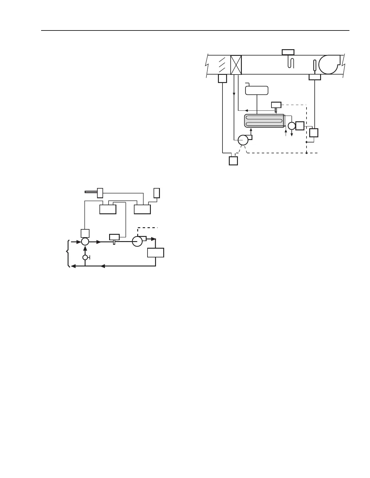
The use of an instantaneous converter (Fig. 120) for heating
water supplied directly to an air heating coil provides fast
response. Control system selection problems are the same as
for the control of a coil supplied with low or medium
temperature water except that a high quality valve with fast
control response is required for HTW.
Fig. 120. Instantaneous Converter Control for HTW
to Glycol Solution for Outdoor Air Preheat.
Where coils are exposed to freezing temperatures, as in a
100 percent outdoor air supply unit, the cost of installing a
foolproof control system plus necessary duct work and dampers
make the use of a water supplied coil questionable. Flow to the
coil should be constant with variable temperature. Better
protection against freezing is obtained by use of a heat transfer
fluid such as a glycol solution.
Glycol solutions used with HTW heating must be closely
monitored. Solutions of ethylene or propylene glycol assume
the corrosivity of the water from which they are prepared and
are oxidized by air into acidic products. The deterioration rate
of inhibitors and stabilizers added to commercial glycol is
influenced by temperature, amount of air in the solution, and,
to some extent, the metals in the piping system. Heat exchanger
surfaces should be kept below 140°C as temperatures above
148°C accelerate deterioration of inhibitors.
If HTW flow is stopped while the air handling unit continues
to operate with below freezing entering air temperature, heat
transfer solution returning to the converter could cause the
converter to freeze. A low-limit duct temperature controller is
recommended to stop the fan if a low air temperature leaving
the coil is sensed.
HTW COILS
Figure 121 shows an acceptable method of mixed air control
when there is a possibility of freezing air passing through the
heating coil. Face and bypass dampers control the heat output
of the coil during normal operation. When the outdoor
temperature rises so that no heat is needed from the coil, valve
V1 closes preventing overheating from the down stream side
of the coil. The low-temperature limit controller senses the air
temperature leaving the coil and opens the valve on sensing a
freezing temperature. Use of a glycol solution as shown in
Figure 120 is recommended.
C2934
OUTDOOR
AIR SENSOR
TO HTW
CONVERTER
ZONE
HIGH-LIMIT
INTERLOCKED
TO CLOSE
HTW VALVE
WHEN
ALL PUMPS OFF
MANUAL
BALANCING VALVE
VALVE V2
CONTROLLER
C2
CONTROLLER
C3
IMMERSION
SENSOR
LOAD