ENGINEERING MANUAL OF AUTOMATIC CONTROL
PNEUMATIC CONTROL FUNDAMENTALS
76
Fig. 29. Double-Seated Valve.
Figure 30 shows three-way globe valve assemblies. The
mixing valve has two inlets and a common outlet. The diverting
valve has a common inlet and two outlets.
BRANCH
LINE
INLET
FLOW
OUTLET
FLOW
C2612
NORMALLY OPEN VALVE
F3
F2
F1
BRANCH
LINE
F1
INLET
FLOW
INLET FLOW
OUTLET FLOW
OUTLET
FLOW
C2615
F2
MIXING VALVE, NORMALLY CLOSED TO
STRAIGHT-THROUGH FLOW
BRANCH
LINE
F1
INLET
FLOW
OUTLET
FLOW
F2
DIVERTING VALVE, NORMALLY OPEN TO
STRAIGHT-THROUGH FLOW
Fig. 30. Three-Way Valve Assemblies.
Three-way valves may be piped to be normally open or
normally closed to the heating or cooling load. If a three-way
valve has linear characteristics and the pressure differentials
are equal, constant total flow is maintained through the common
inlet or outlet port.
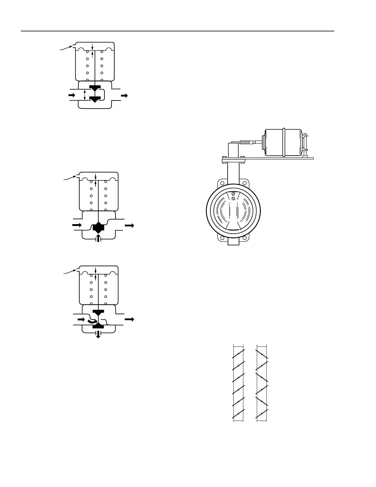
Two- and three-way butterfly valves can be operated by long
stroke pneumatic actuators and appropriate linkage (Fig. 31).
One or two low pressure actuators powered directly by
branchline pressure can operate butterfly valves up to about
300 millimeters, depending on the differential close-off rating
of the valve. For other applications high pressure pneumatic
cylinders can be used to provide the force required by the valve.
A pneumatic positioner provides an appropriate high pres-
sure signal to the cylinder based on a 20 to 100 kPa input
signal.
PARALLEL
BLADES
OPPOSED
BLADES
C2604
Fig. 31. Butterfly Valve Assembly.
For a more detailed discussion of valves, see the Valve
Selection And Sizing section.
DAMPERS
Dampers control the flow of air in air-handling systems. The
most common type of damper, a multiblade louver damper,
can have parallel or opposed blades (Fig. 32).
Fig. 32. Parallel- and Opposed-Blade Dampers.
M10403