ENGINEERING MANUAL OF AUTOMATIC CONTROL
VALVE SELECTION AND SIZING
441
Fig. 17. Equal Percentage Valve Hot Water Application.
Since the valve pressure drop (∆P) should be equal to or
greater than the drop through the heat exchanger and
fittings, 4.82 kPa is used as the valve pressure drop.
For optimum control, a manual balancing valve is
installed in the bypass line to equalize the pressure drops
in the exchanger and bypass circuits.
Substituting the flow of water, density of water, and
pressure drop in the K
v
formula shows that the valve
should have a K
v
of 72.8 or 73.
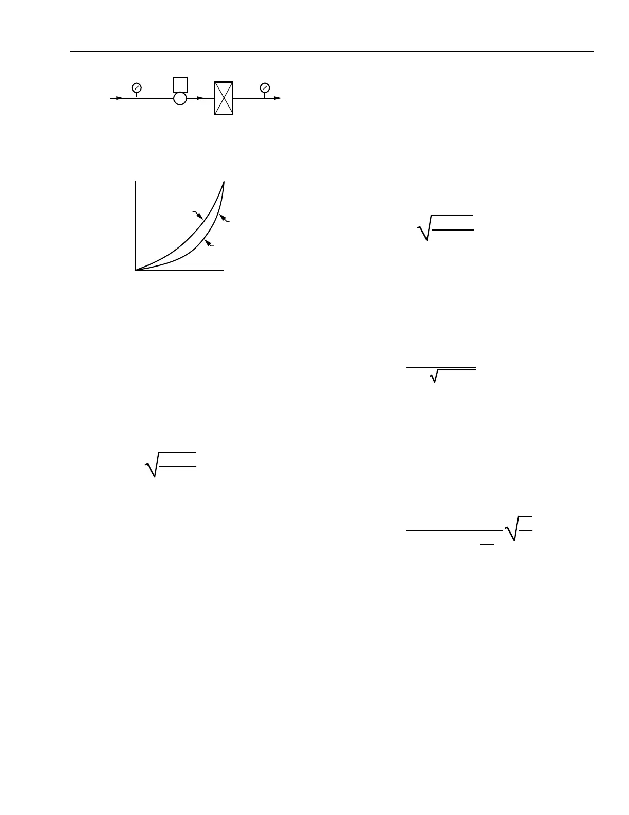
Fig 18. Effect of Pressure Drop
in Hot Water Valve Sizing.
EXAMPLE 4:
A three-way mixing valve is needed for a heat exchanger
application with a bypass line. Water flow is specified at
the rate of 16 m
3
/h. Manufacturer data for the exchanger
indicates a pressure drop of 4.2 kPa through the exchanger
coils.
Use the water valve K
v
formula to determine capacity
index for Valve V1 as follows:
100%
0% 100%
STEM TRAVEL
FLOW AT CONSTANT
PRESSURE DROP
C2340
70%
PRESSURE
DROP
30%
PRESSURE
DROP
IDEAL EQUAL
PERCENTAGE
VALVE
CHARACTERISTIC
Where:
Q = Flow of fluid required to pass through the
valve is 16 m
3
/h.
ρ = Density of water is 1000.
∆P = Pressure drop across the valve. Plans of the
heating system indicate 80-mm supply and
return mains. From an elbow equivalent
table and pipe friction chart found in the
ASHRAE Handbook or other reference
manuals, the calculated pressure drop
through a 80-mm tee and the piping from the
valve and the tee to the exchanger is
0.62 kPa. Heat exchanger pressure drop is
4.2 kPa. Total pressure drop from bypass
connection through the heat exchanger and
to the hot-water input of the three-way valve
is 4.2 kPa + 0.62 kPa or 4.82 kPa.
Select a linear valve providing close control with a
capacity index of 73
STEAM VALVES
Calculate the required capacity index (K
v
) for a valve used
in a saturated steam application, using the formula:
Where:
Q = Quantity of steam in kilograms per hour
required to pass through the valve.
0.224 = A scaling constant.
∆P = Pressure drop in kPa.
P
o
= Absolute outlet pressure of valve in
kilopascals (P
1
– ∆P).
Calculate the required capacity index (K
v
) for a valve used
in a superheated steam application, using the formula:
Where:
Q = Quantity of steam in kilograms per hour
required to pass through the valve.
∆P = Pressure drop in kPa.
P
1
= Absolute inlet in kilopascals.
V
1
= Inlet specific volume in cubic centimeters
per kilogram.
Determining the K
v
for a steam valve requires knowing, the
quantity of steam (Q) through the valve, the pressure drop (∆P)
across the valve, and the degrees of superheat. See QUANTITY
OF STEAM and STEAM VALVE PRESSURE DROP. Then
select the appropriate valve based on K
v
, temperature range,
action, body ratings, etc., per VALVE SELECTION guidelines.
K
v
=Q
ρ
∆P • 10
K
v
=16
1000
4.82 • 10
= 72.8
K
v
=
Q
0.224
∆P • P
o
K
v
=
Q
3.15 –
()
1.55 •
∆P
P
1
V
1
∆P
VALVE VI
C4369
80°C
HOT WATER
SUPPLY
275 kPa
HOT WATER
RETURN
HEATING
COIL
LOCAL
PIPING
15 kPa
DROP
4.54 m /h AT DESIGN,
30 kPa DROP
30% PRESSURE DROP, Kv = 10
70% PRESSURE DROP, Kv = 4.4
CASE B: 425 kPa
CASE A: 345 kPa
3
 Loading...


