ENGINEERING MANUAL OF AUTOMATIC CONTROL
VALVE SELECTION AND SIZING
440
Assume the following:
System flow at design, 225 m
3
/h
Pump pressure at design, 144 kPa
Pump pressure at 90 percent flow, 150 kPa
Pressure across mains at AHU 1 at design flow, 84 kPa
Chiller pressure drop, 36 kPa
Chiller piping loop design pressure drop, 24 kPa
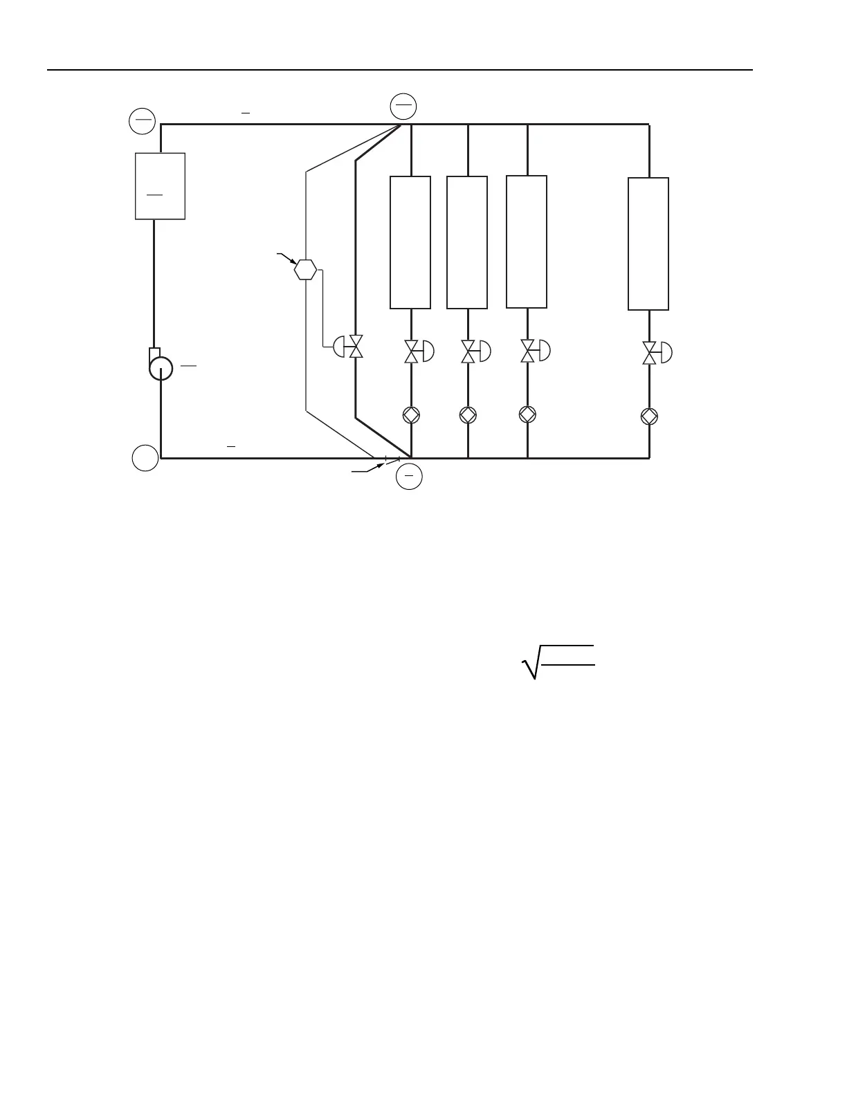
With full system flow, Valve V5 is closed. Pressure drop
across V5 equals the pump pressure minus the friction
drops to V5. Pressure drop across Valve V5 is then
144 kPa – 36 kPa (chiller drop) – 12 kPa (supply drop)
– 12 kPa (return drop) or 84 kPa.
With system flow at 90 percent, the pump pressure rises to
150 kPa, while the friction drops fall to the lower values
shown in Figure 16. For additional information on chiller
bypass operation see Chiller, Boiler, and Distribution
System Applications section. Pressure drop across V5
equals the pump pressure minus the friction drops to V5.
Pressure drop across Valve V5 is then 150 kPa – 28.8 kPa
(chiller drop) – 9.6 kPa (supply drop) – 9.6 kPa (return
drop) or 102.
Substituting the flow of water, specific gravity of water,
and pressure drop in the K
v
formula shows that the Valve
V5 should have a K
v
of 223.
Fig. 16. Chiller Bypass Application.
EXAMPLE 3:
Sizing water valves for heating coils is especially critical.
In Figure 17, a valve with a K
v
of 10 will have 30 percent
of the available pressure drop when full open, while a
valve with a K
v
of 4.4 will have 70 percent of the
available pressure drop. As shown in Figure 18, the valve
with 70 percent of the available pressure drop essentially
provides the equal percentage water flow control,
resulting in linear coil heat transfer and stable temperature
control. The valve with only 30 percent of the available
pressure drop has a more linear flow control which results
in nonlinear coil heat transfer. See EQUAL
PERCENTAGE VALVE section for further information.
K
v
= 225
1000
102 • 10
= 222.8
RETURN
SYSTEM STRAINER
HEAT/
COOL
COIL
1
V1
B1
HEAT/
COOL
COIL
2
V2
B2
HEAT/
COOL
COIL
3
V3
B3
HEAT/
COOL
COIL
4
V4
B4
V5
PUMP
SUPPLY
11.4 L/S
PER
AHU COIL
DP
M15321
CHILLER
36
40.4
PD
12
9.6
12
9.6
PD
12
9.6
PD
ZERO REFERENCE
0
96
111.6
36
28.8
NUMBERS IN CIRCLES = GAGE PRESSURES
PUMP INLET = ZERO FOR SIMPLICITY
TOP NUMBERS = FULL FLOW
BOTTOM NUMBER = 90% FLOW
PD = PRESSURE DROP
144
150
DP SETPOINT = 102 kPa
 Loading...


