ENGINEERING MANUAL OF AUTOMATIC CONTROL
CHILLER, BOILER, AND DISTRIBUTION SYSTEM CONTROL APPLICATIONS
320
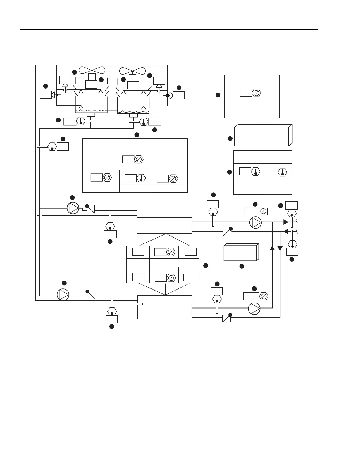
DUAL COOLING TOWER VARIABLE SPEED FAN CONTROL
Functional Description
Fig. 31. Dual Cooling Tower Variable Speed Fan Control Graphic
Item No. Function
1,2 Dual dynamic pump symbols indicate pump
operational status.
3 OA Conditions dictate freeze-protection and
optimized setpoint control strategies.
4-7 Valves provide tower isolation, modulating
low limit condenser water control when OA
temperature is above freezing, and two
position low limit operation when OA
temperature is below freezing.
8,9 Indicates tower fans speed (percent).
10 Input for common condenser water
temperature control.
11 Optimum condenser water temperature
calculation based upon OA WB.
12-22 Operator information.
23 Isolates towers if required.
24 Icon, for dynamic control and setpoint
display.
25 Icon to select tower low load control dynamic
sequence display.
CHILLER
CONTROL
100
0
33
100
0
33
V1T
V2T
V1S
V2S
TOWER ISOLATION
SELECTOR
0 = NO TOWERS ISOLATED
1 = TOWER 1 ISOLATED
2 = TOWER 2 ISOLATED
OUTSIDE AIR
TEMPERATURE
TOWER FAN CONDENSER WATER
TEMPERATURE SETPOINT EQUALS OA WET BULB
TEMPERATURE PLUS
DEGREES
MINIMUM
CURRENT
MAXIMUM
CHILLER 1
STATUS
CHILLER 2
SETPOINTS/
SEQUENCES
23
DRY
BULB
WET
BULB
PERCENT LOAD
MAX
CURRENT
COOLING
TOWER 1
COOLING
TOWER 2
AUTO
21
71
7.0
85
100
100
19
17
25
16
22
20
18
14
15
10
11
1
2
6
13
12
4
5
8
9
7
24
3
25.525.5
25.5
32.5
13
7.1
13
ON
30.5
21.5
78
7
29.5
AUTO
78
OFF
00
0
M15264