ENGINEERING MANUAL OF AUTOMATIC CONTROL
AIR HANDLING SYSTEM CONTROL APPLICATIONS
252
HEATING, COOLING, HUMIDIFICATION, AND DEHUMIDIFICATION CONTROL
WITHOUT DEAD-BANDS
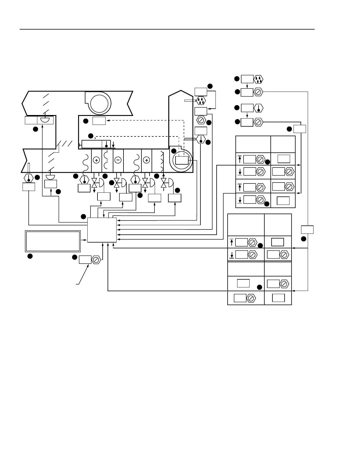
Functional Description
Item
No. Function
1-3 Control system energizes when fan is turned
on (See FAN SYSTEM START-STOP
CONTROL).
4-6 Manual positioning value determines
minimum ventilation mixing damper position.
7 Operator information, outdoor air temperature.
8 Economizer enables free cooling when OA is
suitable.
9 Operator information, MA temperature.
10,27 Heating coil valve modulates to keep reheat
coil entering air from getting too low.
11-16 Space temperature PI loop resets setpoint of
reheat coil SA PI loop to maintain constant
space temperature.
17,18 Chilled water valve modulates in sequence
with mixing dampers as required to maintain
SA PI setpoint.
19 Chilled water coil leaving air temperature
lowered if required for dehumidification.
20-26 Space humidity PI control loop modulates
humidifier valve to maintain space relative
humidity, subject to an SA high limit
humidity PI loop.
27 Control program coordinates ventilation,
heating, cooling, humidification,
dehumidification, and fan interlocks.
M15180
OA
EA
RA
SA
2
ON
ON
1
83
5
3
83
4
9 10
18
28
NORMAL
ECONOMIZER DECISION.
REFER TO PREVIOUS
ECONOMIZER OPTIONS
OA MINIMUM SETPOINT
(NOTE: THE TEST AND
BALANCE INITIAL
VALUE FOR PROPER
VENTILATION IS 22)
8
6
CONTROL
PROGRAM
22
15
27
23
19
13
21 45
55
100
COOL COIL
LEAVING AIR
TEMPERATURE
SETPOINT
HUMIDI-
FICATION
DEMAND
HUMIDIFIER
VALVE POSITION
0
0
100
17
14
41
13 40
45
SUPPLY AIR
TEMPERATURE
SETPOINT
COOLING
DEMAND
0
100
24
13
16 13
7
100
0
SUPPLY
FAN
PERCENT
OPEN
N.C.
CW
N.O.
N.C.
24
25
16
52
13.5
9
88
11 0
26
20
21
52
50
11
12
23.5
23.5
35
22
50
SPACE
OA
REHEAT
13