MICROPROCESSOR-BASED/DDC FUNDAMENTALS
146
ENGINEERING MANUAL OF AUTOMATIC CONTROL
staged by a PI algorithm with software heat anticipation. See
Figure 15. During reheat, the control mode changes to constant
volume, variable discharge temperature.
4. Develop a detailed flowchart of the control sequence
using either DDC operators or a programming logic flow
diagram. Programs written totally in a high-level language
use the logic flow diagram.
5. Write the program using either DDC operators (Table 1)
or high-level language statements.
An example of this approach follows for control of a hot
water converter:
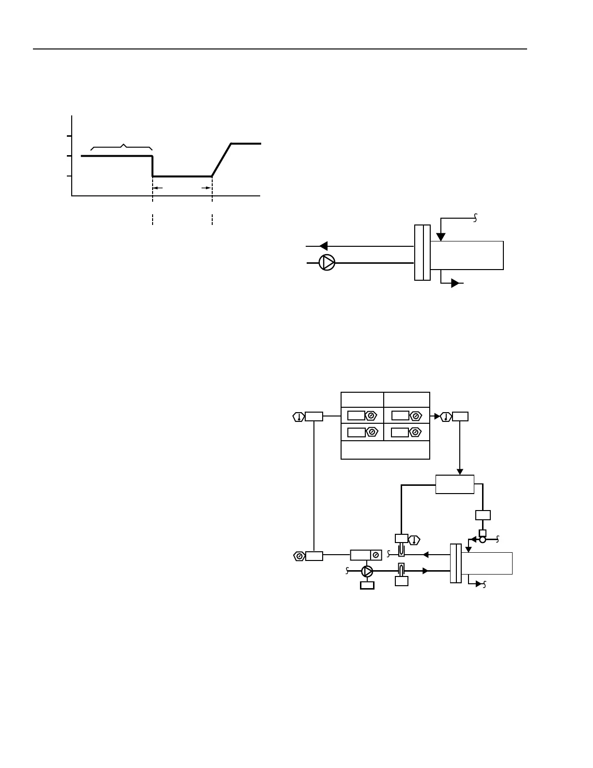
Step 1—Develop flow schematic of the process to be controlled
(Fig. 16).
MAX
FLOW
REHEAT
FLOW
MIN
FLOW
COLD HOT
CONSTANT VOLUME,
VARIABLE DISCHARGE TEMPERATURE
CONSTANT
DISCHARGE
TEMPERATURE,
VARIABLE
VOLUME
C2686
COOLING
SETPOINT
HEATING
SETPOINT
SPACE LOAD
PRIMARY AIRFLOW (CFM)
DEAD BAND
Fig. 15. Control Sequence for VAV Cooling with
Sequenced Electric Reheat.
SYSTEM-LEVEL CONTROLLER
System-level controllers are variable-function devices applied
to a wide variety of mechanical systems. These controllers can
accommodate multi-loop custom control sequences and have
control integrated with energy management and building
management functions. The examples that follow cover direct
digital control functions for a system-level controller. Integrated
building management functions are covered in the Building
Management System Fundamentals section.
Where the examples indicate that user entered values are
furnished (e.g., setpoint), or that key parameters or DDC
operator outputs will have display capability, this represents
sound software design practice and applies whether or not the
controller is tied into a central building management system.
Data is entered or displayed in non-BMS applications by a
portable operator’s terminal or by a keypad when display is
integral with the controller.
A five-step approach can be used to define DDC programs.
1. Develop a system flow schematic as a visual
representation of the process to be controlled. The
schematic may be provided as a part of the plans and
specifications for the job. If not, a schematic must be
created for the system.
2. Add actuators, valves, sensors, setpoints, and operational
data required for control and operation.
3. Write a detailed sequence of operation describing the
relationship between inputs, outputs, and operational data
points.
M15035
STEAM TO
HOT WATER
CONVERTER
HOT WATER RETURN
HOT WATER SUPPLY
STEAM
Fig. 16. Schematic of Steam to Hot Water Converter.
Step 2—Identify required sensors, actuators, and operational data
(Fig. 17). Refer to the Chiller, Boiler, and Distribution
System Control Applications section for a symbol legend.
Fig. 17. Schematic Illustrating Sensors, Actuators, and
Operational Data for Steam to Hot Water Converter.
M15139
STEAM TO
HOT WATER
CONVERTER
STEAM
VALVE
60
ON
HOT
WATER
RETURN
AUTO
11
67
58
PERCENT
OPEN
IN OUT
SP
PID
-6
67
HOT WATER
PUMP
OUTSIDE
AIR
SETPOINT
OUTSIDE
AIR
HOT WATER
SETPOINT
-20
50
16
77
HOT WATER RESET
SCHEDULE
PUMP-ON
SETPOINT
 Loading...


