ENGINEERING MANUAL OF AUTOMATIC CONTROL
AIR HANDLING SYSTEM CONTROL APPLICATIONS
214
SPECIFICATIONS
See FAN SYSTEM START-STOP CONTROL.
Anytime the supply fan runs, the OA, EA, and RA dampers
shall be modulated by an MA PID control loop to satisfy the MA
temperature setpoint down to a minimum ventilation position.
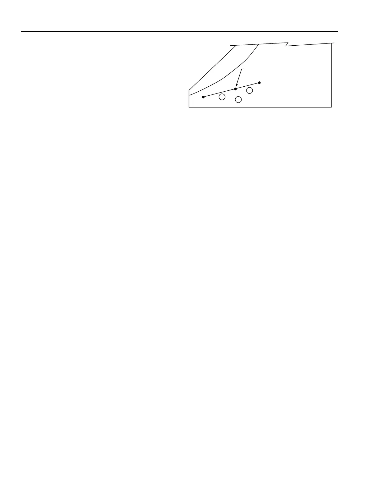
PSYCHROMETRIC ASPECTS
In the following chart it is assumed that:
1. The manual positioning value is set for one-third
minimum OA.
2. RA condition is 24°C DB and 15°C WB.
3. OA condition is 4°C DB and 1.5°C WB.
4. The MA controller is set at 16°C.
5. The desired MA temperature can be maintained until the
OA temperature falls below the temperature at which only
minimum OA is admitted and until the OA is greater
than 16°C.
The following results are obtained:
Item
No. Explanation
1 As OA temperature varies between –1.5°C
and 16°C, the MA condition lies on the 16°C
DB line.
2 As OA temperature rises above 16°C DB, 100
percent OA is admitted, and the MA condition
will lie to the right of the 16°C DB line.
3 As OA temperatures fall below –1.5°C DB,
one-third OA (set by the manual positioning
switch) is admitted, and the MA condition
will lie to the left of the 16°C DB line.
C3236
17.5°C DB MA
CONTROLLER SETPOINT
RA 24°C DB, 15°C WB
MA
OA
4°C DB, 1.5°C WB
3
2
1
 Loading...


