ENGINEERING MANUAL OF AUTOMATIC CONTROL
BUILDING AIRFLOW SYSTEM CONTROL APPLICATIONS
269
If this is done on a VAV system at design load, as the VAV
boxes require less cooling and less airflow, the supply fan
capacity reduces, and the inlet pressure to the supply fan
becomes less negative as the fan unloads. As the filter inlet
pressure becomes less negative, less OA is drawn into the
system which is unacceptable from a ventilation and IAQ
perspective. VAV systems therefore require design
considerations to prevent non-economizer occupied mode
ventilation from varying with the cooling load. This may be
accomplished in several ways.
The dampers may be set at design load as for a constant air
volume system, and the filter inlet pressure noted. Then the
noted filter inlet negative pressure can be maintained by
modulating the return air damper. Keeping this pressure constant
keeps the OA volume constant. This method is simple but
requires good maintenance on the OA damper and linkage,
positive positioning of the OA damper actuator, and the
balancing person to provide the minimum damper position and
the pressure setpoints.
Another positive method is to provide a small OA injection
fan set to inject the required OA into the AHU mixing box
during occupied periods (the OA damper remains closed). The
fan airflow quantity may be controlled by fan speed adjustment
or inlet damper setting and sensed by an airflow measuring
station for closed loop modulating control. This basic method
is positive and relatively maintenance free, but like the pressure
control method, it requires a balancing person to make
adjustments. This closed loop control method is more costly
and requires keeping the airflow pickup/sensor clean, but it
allows simple setpoint entry for future adjustments.
A minimum OA damper may be provided for the occupied
OA volume requirement. An airflow measuring station in the
minimum OA duct is required to modulate the minimum OA
damper in sequence with the RA damper to maintain a constant
volume of OA. This method is more costly than the first method,
but it allows convenient software setpoint adjustments.
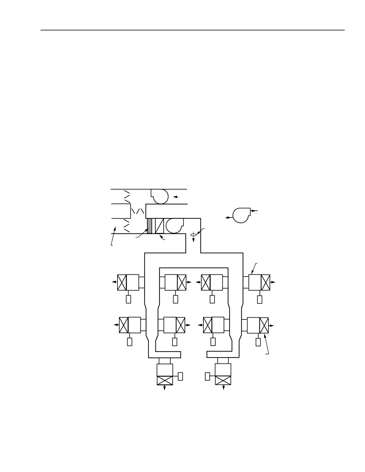
Fig. 2. Single Duct Constant Air Volume System.
RETURN
AIR FAN
OUTDOOR
RELIEF (OR)
EA
RA
OA
16.5 m
3
/s
CONSTANT
COOLING
COIL
FILTER
OUTDOOR AIR
2.5 m
3
/s
MINIMUM
19.0 m
3
/s
CONSTANT
REMOTE
EXHAUST FAN
0.7 m
3
/s
TT
INTERIOR ZONES
T
TTT
T
T
REHEAT
COILS
PERIMETER
ZONES
C4073
EXFILTRATION
1.8 m
3
/s
CAV AIR
TERMINAL
UNITS
T
SUPPLY
AIR FAN
T
 Loading...


