ENGINEERING MANUAL OF AUTOMATIC CONTROL
BUILDING AIRFLOW SYSTEM CONTROL APPLICATIONS
289
M12216
SUPPLY
AIR
SUPPLY
AIR TO
LAB
GENERAL
EXHAUST
AIR
EXHAUST
AIR
FUME
HOOD
DAMPER
ACTUATOR
SUPPLY
AIR TO
CORRIDOR
DIFFERENTIAL
PRESSURE
SENSOR
VELOCITY
SENSOR
SUPPLY AIR
DAMPER
ACTUATOR
EXHAUST AIR
DAMPER ACTUATOR
AIRFLOW
SENSOR
LAB AIRFLOW
CONTROLLER PANEL
M12215
SUPPLY
AIR
SUPPLY
AIR TO
LAB
GENERAL
EXHAUST
AIR
EXHAUST
AIR
DAMPER
ACTUATOR
OR
AIR VALVE
AIRFLOW
SENSOR
SUPPLY
AIR TO
CORRIDOR
VELOCITY
SENSOR
DAMPER
ACTUATOR
OR AIR
VALVE
AIRFLOW
SENSOR
DAMPER ACTUATOR
OR AIR VALVE
AIRFLOW
SENSOR
LAB AIRFLOW
CONTROLLER PANEL
OR
SASH
SENSOR
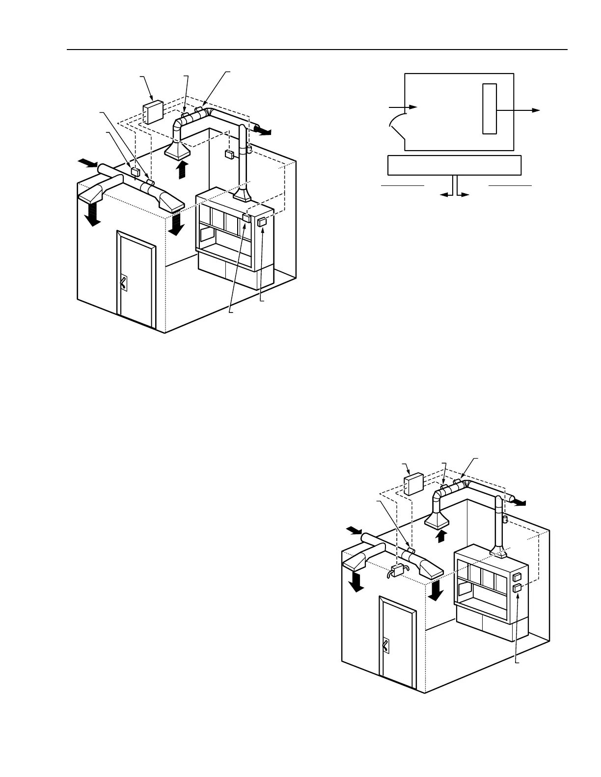
Fig. 46. Airflow Tracking Control.
Airflow sensors located in all supply and exhaust ducts
provide flow signals which can be compared by a controller.
Sensor locations must meet the manufacturers minimum
installation guidelines, such as velocity range and length of
straight duct before and after the sensor, to ensure accuracy.
Materials and finishes for sensors in exhaust ducts exposed to
corrosive fumes must be carefully selected.
If future flexibility and changing lab configurations are
important considerations, then flow sensor location, duct size,
supply airflow rate, and control system design should all include
capabilitiy to be modified in the future.
A characteristic of airflow tracking is stability of the system in
the face of breaches to the lab envelope. This is most often lab
door openings. In a laboratory maintained at a negative pressure,
the space static pressure increases and the air velocity through all
openings drops significantly when a door opens. Figure 47 shows
a laboratory example with a single fume hood, a single door 1m
wide x 2m high (2m
2
), and a crack area estimated at 0.05 m
2
. If
the fixed airflow tracking differential is 0.1 m
3
/s, the average
velocity through the cracks would be 2.0 m/s which is more than
adequate for containment. However, when the door opens, the
average velocity in this example decreases to 0.05 m/s which is
marginal to inadequate for containment.
However, the ability of the tracking system to quickly
(usually within several seconds) react and compensate for door
openings and other breaches is a positive characteristic of this
control method.
Fig. 47. Airflow Tracking Example with
Door Closed and Opened.
Supply duct pressure and building pressurization control are
simpler and more stable with airflow tracking because they are
less affected by this type of unexpected upset. The supply duct
pressure control remains stable due to fewer disruptions. Building
pressurization, defined as the difference between total air leaving
the building and the total air entering, remains the same.
Direct pressure control (Fig. 48) provides the same control
function as airflow tracking but its characteristics are quite
different. Direct space pressurization control senses the
differential pressure between the space being controlled and a
reference space which is usually an adjacent space or hallway.
Figure 49 shows a similar example of negative space
pressurization utilizing direct pressure control. If the airflow
through the hood is 0.5 m
3
/s and the pressure control reduces
the supply airflow when the door is opened, the average velocity
through openings drops from 2.0 m/s to 0.25 m/s.
Fig. 48. Direct Pressure Control.
CRACK AREA = 0.05 m
2
SUPPLY
DOOR
0.4 m
3
/s
0.5 m
3
/s
0.7 m
3
/s
2 m
2
FUME HOOD
EXHAUST
DOOR CLOSED
= 2 m/s
DOOR OPENED
= 0.05 m/s
DIFFERENTIAL = EXHAUST – SUPPLY
= 200 CFM
C4076
VELOCITY = 0.1 2.05
÷
VELOCITY = 0.1
0.05
÷
 Loading...


