ENGINEERING MANUAL OF AUTOMATIC CONTROL
CHILLER, BOILER, AND DISTRIBUTION SYSTEM CONTROL APPLICATIONS
324
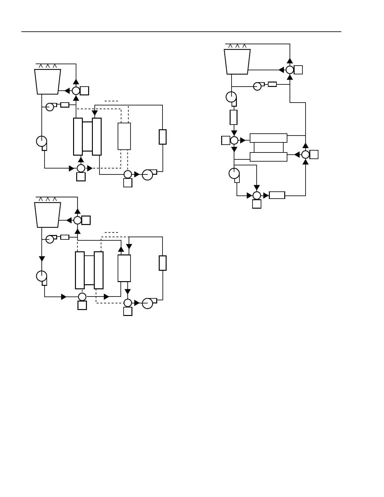
Fig. 35. Free Cooling by Interconnecting
Water Circuits.
When the chiller is shut down during free cooling operation,
the normal chilled water supply temperature control is bypassed
and the chilled water supply temperature is determined by the
tower water temperature. The normal cooling tower water
control cycles tower fans and modulates the tower bypass valve
to maintain a setpoint in the 18°C to 29.5°C range but cooling
tower water is controlled at 1.5°C to 7°C when used directly
for cooling.
During free cooling the fans may be manually turned on if
there is no danger of supply water being too cold or too much
energy being used by a winterized cooling tower. However, if
either condition exists, the tower water temperature control
should be in operation at all times to maintain a free cooling
temperature of 1.5°C to 7°C.
The changeover from free cooling to chiller operation may
be manual or automatic. Changeover sequence should change
the tower water controller setpoint first, then change the heat
exchanger valves when temperatures are proper for the new
mode of operation.
Following is a tower-free-cooling example using plate-frame
heat exchangers for the dual chiller system shown in the DUAL
CENTRIFUGAL CHILLER example. The DUAL COOLING
TOWER VARIABLE SPEED FAN CONTROL example is also
relevant.
CONDENSER
COMPRESSOR
EVAPORATOR
LOAD
CHILLED
WATER
PUMP
CONDENSER
WATER PUMP
COOLING
TOWER
TOWER HEATER
(OPTIONAL)
C2698
FILTER
In Figure 34, condenser and chilled water flows are diverted
from the chiller to a heat exchanger.
Fig. 34. Free Cooling Using
Auxiliary Heat Exchanger.
In Figure 35, condenser and chilled water circuits are
interconnected bypassing the chiller. In this configuration
providing tower water treatment and filtering and pumping
capacity for proper cooling tower flow are major considerations.
CONDENSER
COMPRESSOR
EVAPORATOR
CONDENSER
WATER
PUMP
COOLING
TOWER
TOWER HEATER
(OPTIONAL)
C2699
LOAD
WATER FLOW DURING CHILLER COOLING
HEAT
EXCHANGER
HEAT
EXCHANGER
INDICATES NO FLOW
NOTE:
CONDENSER
COMPRESSOR
EVAPORATOR
CONDENSER
WATER
PUMP
COOLING
TOWER
TOWER HEATER
(OPTIONAL)
LOAD
WATER FLOW DURING FREE COOLING
INDICATES NO FLOW
NOTE: