ENGINEERING MANUAL OF AUTOMATIC CONTROL
CHILLER, BOILER, AND DISTRIBUTION SYSTEM CONTROL APPLICATIONS
354
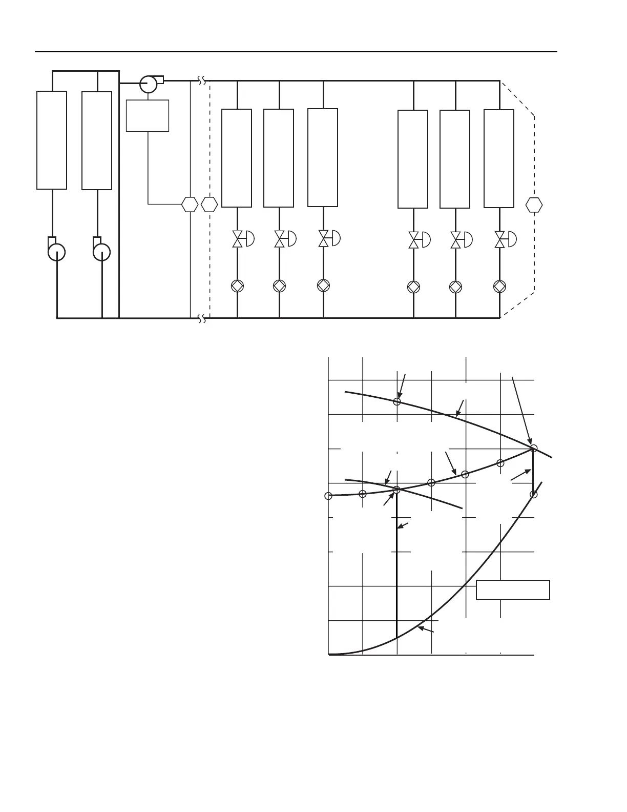
Fig. 79. Variable Speed Pump Control
Fig. 80. Fixed Setpoint with PI,
Variable Speed Pumping Control
DP
DP
C
H
I
L
L
E
R
1
C
H
I
L
L
E
R
2
HEAT/
COOL
COIL
1
V1
B1
HEAT/
COOL
COIL
2
V2
B2
HEAT/
COOL
COIL
3
V3
B3
HEAT/
COOL
COIL
4
V4
B4
HEAT/
COOL
COIL
5
V5
B5
HEAT/
COOL
COIL
6
V6
B6
3
VARIABLE
SPEED
DRIVE
2
1
DP
M15066
AHU 1 requires a 84 kPa differential pressure (24 kPa for
the coil, 24 kPa for the valve, and 36 kPa for the balancing
valve), for full flow. If 84 kPa is available at AHU 1, all other
AHUs will have at least the required design differential pressure.
Controlling the pump with a sensor positioned as shown for
DP-2 set for 84 kPa is acceptable.
Locating the sensor (DP-3) at AHU 6 and set for the 48 kPa
required by AHU 6 will not work when only AHU 1 is operating.
With these conditions DP-3 maintains a maximum drop of only
48 kPa across AHU 1 which needs a 84 kPa differential pressure
because of the balancing valve. If the sensor is positioned at
AHU 6, the setpoint must still be 84 kPa if the system is to
operate satisfactorily with non-symmetrical loading.
DP-1 located at the variable speed drive (VSD) is the most
convenient place. It requires the DP-2 setpoint plus the friction
losses between the pump and AHU 1.
Figure 80 shows the operating curve of the system with the
differential pressure sensor located in the DP-2 position and
set for 84 kPa. With each AHU at one-third flow, the speed is
1412 RPM, which produces a 84 kPa differential pressure at
AHU 1 with 25 L/s system flow. When the coils are equally
loaded at one-third flow, each control valve takes a 78 kPa
drop. In this configuration the pump never operates much below
the 1400 rpm speed because of the 84 kPa setpoint.
PRESSURE IN kPa
FULL LOAD
OPERATING POINT
PUMP CURVE
@ 1750 RPM
144
126
108
90
72
54
36
18
0
0 12.5 25 37.5 50 62.5
SYSTEM CURVE FOR STATIC
ELEMENTS OF SYSTEM (CHILLER,
PIPING, FITTINGS, BALANCING
COCKS, COILS, STRAINERS, ETC.)
OPERATING POINT @
25 L/s & 1750 RPM
OPERATING POINTS LINE AS FLOW
VARIES FROM 75 L/s TO ZERO L/s
WITH 84 kPa MAINTAINED ACROSS
AHU 1
PUMP CURVE
@ 1412 RPM
75
OPERATING POINT
WITH EACH
CONTROL VALVE
AT ONE THIRD
FLOW AND PUMP
AT 1412 RPM
EACH CONTROL
VALVE @ ONE
THIRD FLOW
(PRESSURE
DROP ACROSS
VALVES 78 kPa)
EACH
CONTROL
VALVE FULL
OPEN AT
12.5 L/s &
24 kPa
DROP
PUMP REQUIRED:
75 L/s @ 108 kPa
M15290
FLOW IN L/s
 Loading...


