PSYCHROMETRIC CHART FUNDAMENTALS
ENGINEERING MANUAL OF AUTOMATIC CONTROL
45
Fig. 14. Chart No. 1.
The outdoor air (–18°C at 75 percent rh) must be heated to a
comfortable indoor air level. If the air is heated to 21°C, for
example, draw a vertical line at that dry-bulb temperature. The
intersection of the dry-bulb line and the moisture line determines
the new condition. The moisture content is still 0.55 grams of
moisture per kilogram of dry air, but the relative humidity drops
to about 4.5 percent (Point A, Fig. 14). This indicates a need to
add moisture to the air. Two examples of the humidifying
process follow.
EXAMPLE 1:
Determine the amount of moisture required to raise the
relative humidity from 4.5 percent to 35 percent when the air
temperature is raised from –18°C to 21°C and then maintained
at a constant 21°C.
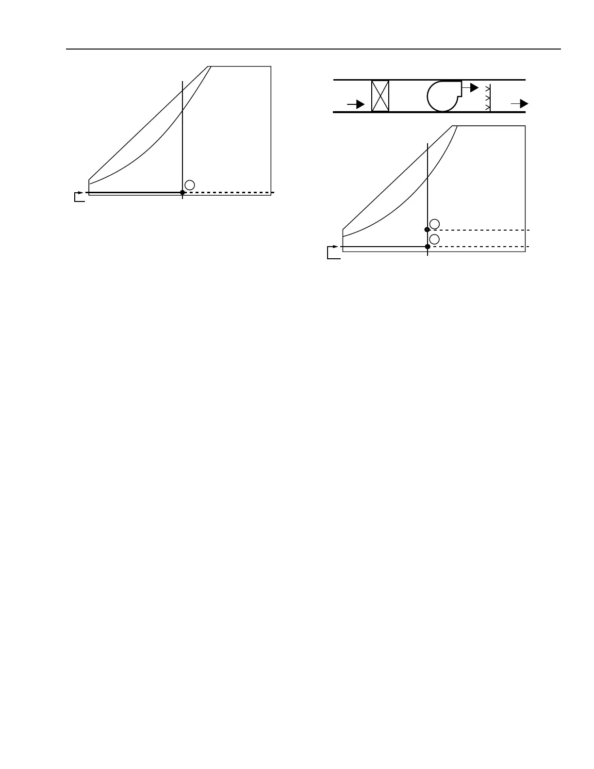
Figure 15 provides an example of raising the relative humidity
by adding moisture to the air. Assume this example represents
a room that is 9 by 12 meters with an 2.5 meter ceiling and two
air changes per hour. Determine how much moisture must be
added to raise the relative humidity to 35 percent (Point B).
To raise the relative humidity from 4.5 percent (Point A) to
35 percent (Point B) at 21°C, the moisture to be added can be
determined as follows:
1. The moisture content required for 21°C air at 35 percent
rh is 5.5 grams of moisture per kilogram of dry air.
2. The moisture content of the heated air at 21°C and
4.5 percent rh is 0.55 grams of moisture per kilogram of
dry air.
3. The moisture required is:
5.5 g/kg – 0.55 g/kg = 4.95 grams of moisture
per kilogram of dry air
Line A-B, Figure 15, represents this humidifying process on
the psychrometric chart.
Fig. 15.
The space contains the following volume:
9m x 12m x 2.5m = 270 cubic meters
Two air changes per hour is as follows:
2 x 270m
3
= 540 cubic meters per
hour
or
540 ÷ (60 x 60) = 150 liters per second
This amount of air is brought into the room, heated to 21°C,
and humidified. Chart No. 2 (Fig. 13) illustrates that outdoor
air at –18°C has a volume of 0.712 cubic meters per kilogram.
The reciprocal of this provides the density or 1.404 kilograms
per cubic meter. Converting the cubic meters per hour of air to
kilograms per hour provides:
540 m
3
/hr x 1.404 kg/m
3
= 758.2 kilograms of air
per hour
For the space in the example, the moisture that must be
added is:
758.2 kg/hr x 4.95 g/kg = 3753 grams
= 3.75 kilograms of
water per hour
EXAMPLE 2:
Determine the moisture required to provide 24°C air at
50 percent rh using 10°C air at 52 percent rh.
In this example, assume that 4700 liters of air per second must
be humidified. First, plot the supply air Point A, Figure 16, at
10°C and 52 percent rh. Then, establish the condition after the air
is heated to 24°C dry bulb. Since the moisture content has not
changed, this is found at the intersection of the horizontal, constant
moisture line (from Point A) and the vertical 24°C dry-bulb
temperature line (Point B).
C4330
A
21°C DB
4.5% RH
0.55 g/kg
FROM CHART 2
SUPPLY FAN
4700 L/s
21°C DB
35% RH
B
A
-18˚C DB
75% RH
HEATING COIL
21°C DB
4.5% RH
4.5% RH
35% RH
5.5 g/kg
0.55 g/kg
21°C DB
FROM CHART 2
C4331
DA
OA