5
Galaxy 2 Series Installation Manual
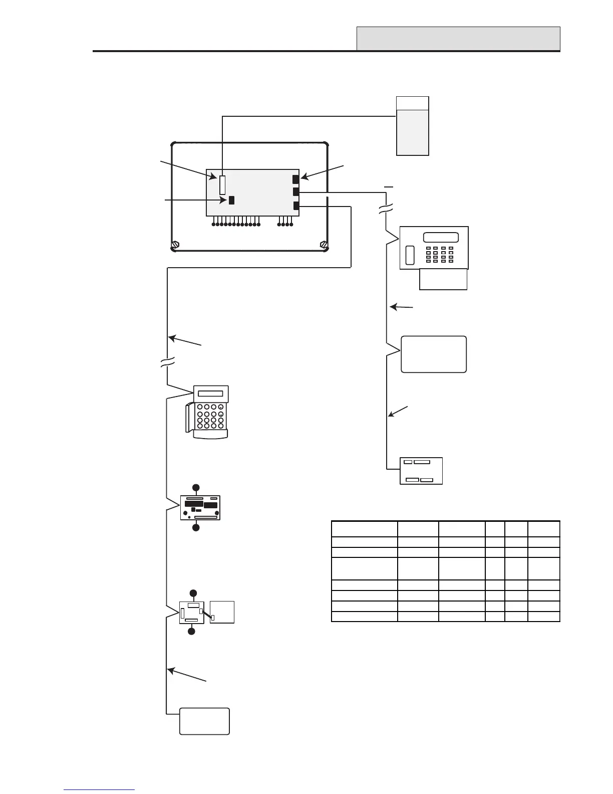
SECTION 3: SYSTEM ARCHITECTURE
Figure 1. Galaxy 2 Series System Configuration
Architecture
12 on-board zones
Galaxy 2-44
PCB
Trigger
Header
12-way ribbon cable
External
Communicator
ECP BUS (2 44+ only)
4 outputs
Phone line
Serial Port to PC
Maximum cable length
from panel to last module
on line is 100m
6160 keypad (4)
(optionally with
built-in
receiver/keyprox)
Note: maximum of
2 receivers/keyproxes
ECP zone expander
8 zone, 4 output (3)
5800 RF
receiver (2)
Standard 4-core cable
spurred or T wired
Note: A maximum of 4 keypads
(including keyprox) can be
connected to the RS485 line.
GALAXY 44 V1.0
09:51 01/08/04
1
2
3
A
4
5
6
B
7
8
9
ent
*
0
#
esc
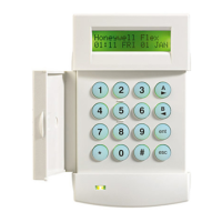
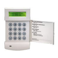
Mk7 LCD
Keypad/Keyprox
(4)
Wireless Receiver (2)
8 zones
4 outputs
8 zones
4 outputs
Power Unit (4) P025
or
Power RIO (4) P026
RIO (4)
C072
OR
RS485 BUS
Twisted pair screened cable
Belden 8723 equivalent.
Daisy chain configuration only.
Maximum cable length
from panel to last module
on line is 1Km
MODULE
TOTAL
QTY
ADDRESSES
AVAILABLE
ECP RS485 PLUG-ON
Keypads 4 0,1, 2, 3 4 4
Keyprox 4 0,1, 2, 3 2 2
Expanders* 4 on RS485
or
3 on ECP
2, 3, 4, 5 3 4
RF Receivers 2 4, 5 2 2
PSU Control/RIO 4 2, 3, 4, 5 - 4
GSM (2-44+ only) 1
---1
2-way Voice (2-44+ only 1
---1
* Only the first expander can be used on the 2-20

 Loading...