17
Galaxy 2 Series Installation Manual
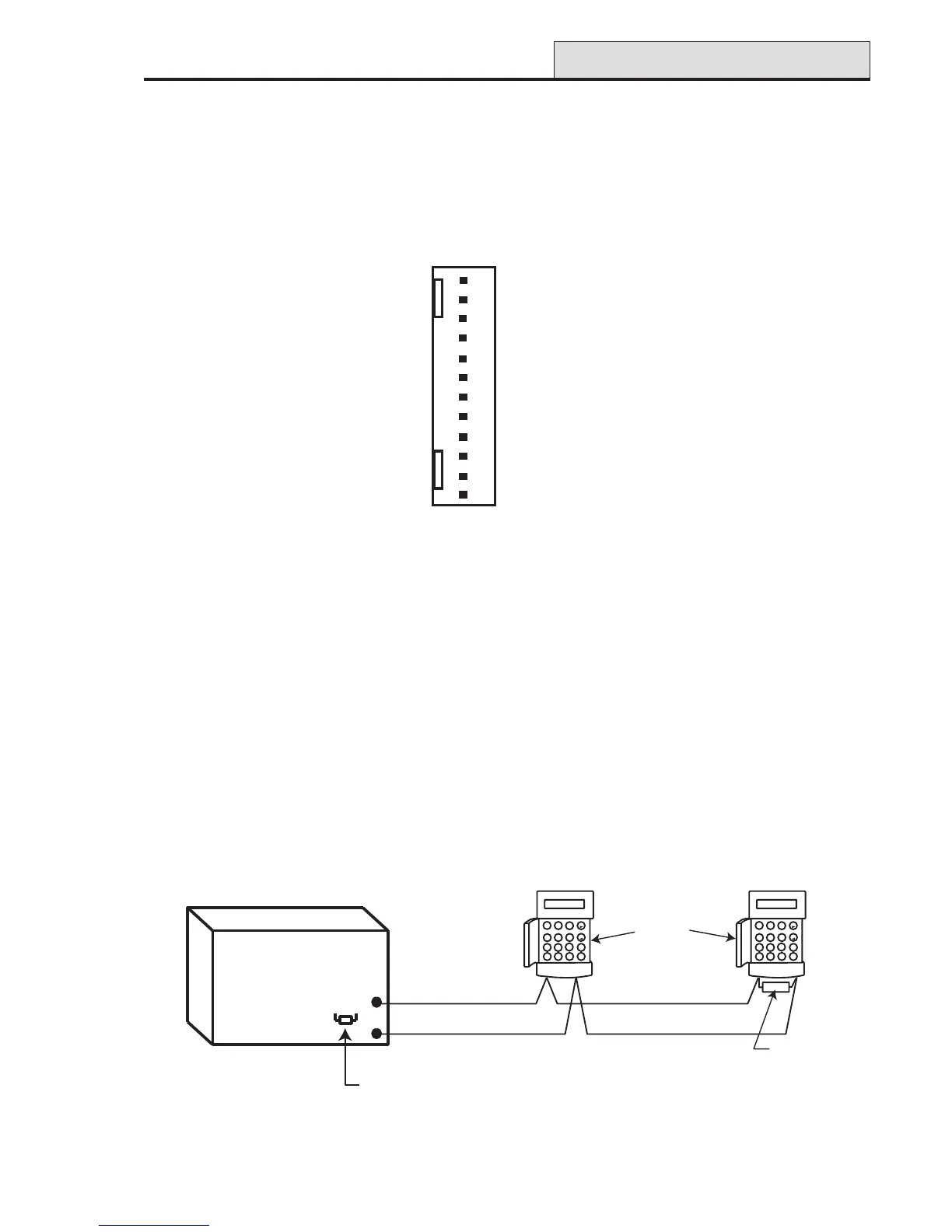
Figure 12. Daisy-chain Configuration
Data Buses
Two separate data buses are available to connect the Galaxy 2–44+ panel to its peripherals.
Communication between the Galaxy 2–44+ control panel and the peripherals attached to it (see Figure 1),
takes place on the data bus. The control panel constantly monitors the peripherals attached to it. A break in
the communication from any of the peripherals generates a tamper alarm.
RS485 Wiring Configurations
The system must be wired in a daisy-chain configuration. That is the A line from the previous peripheral is
connected to the A terminal of the current peripheral and then on to the A line of the next peripheral.
The RS485 (AB) line must have a 680 Ω resistor fitted across the A and B terminals of the last peripheral on
the line.
Figure 11. Trigger Header
Inputs
Line Fault: This input tells the panel that the communicator has a telephone line fault (active low).
Reset: This input from the communicator resets the panel on a low to high signal (negative removed).
Supply
A 100 mA, 12V output is also provided. The output is fused by the on-board AUX FUSE (F2).
Trigger Header

 Loading...