30
Galaxy 2 Series Installation Manual
Installation Instructions
The installation and wiring must be performed by a competent engineer. The Galaxy Power Supply Unit must
be connected to the a.c. mains supply (230/240 Va.c. 50Hz) via a fused connection outlet. The fuse in the
mains outlet must not exceed 3A.
The Galaxy Power Supply Unit comes installed in the metal enclosure base. The installation procedure of the
panel base is as follows:
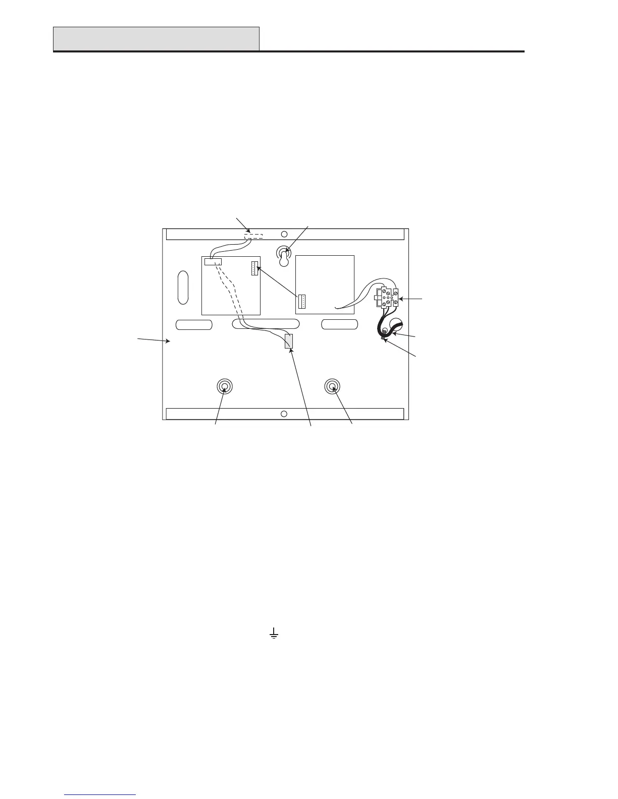
1. Route the mains cable through the hole on the right hand side of the enclosure base. Securely anchor
the cable to the box using the tie-wrap as shown in the following Figure:
Tie wrap
Mains cable
Terminal
block
Keyhole
slot (top)
Enclosure
base
Attaching hole
Attaching hole
Control
Unit
Power
Block
Off-Wall
Tamper
Micro-switch
Lid Tamper
Microswitch
6-w
ay jum
per lead
from
pow
er block
to control unit
Figure 21. Enclosure Base
2. Secure the panel base to the wall using three 1.5" No. 8 round head steel screws through the holes
provided.
The mains cable used must be a three core type (with green/yellow earth insulation) of adequate current
carrying capacity.
NOTE: The mains cable must satisfy the requirements stated in BS6500.
3. Connect the mains cable to the mains terminal block as follows:
• blue wire to the terminal marked N (Neutral)
• green/yellow wire to the terminal marked (Earth)
• brown wire to the terminal marked L (Live)
NOTE: No other connections to the mains connector are permitted.
All wiring must be in accordance with the latest edition of the IEE Wiring Regulations, BS7671 (Requirements
for Electrical Installations).
4. Power up by applying mains first. This unit can be powered up from the battery by momentarily shorting
LK10. Never leave LK10 connected, as deep discharge of the battery will occur. LK10 is for start-up
only.
PSU (cont’d)

 Loading...